Execute States in Parallel
You can set a Stateflow® chart to activate every state in a level of hierarchy on the same step by enabling parallel decomposition in the parent chart or state.
When a chart or state that uses parallel decomposition becomes active, every direct child of the chart or state also becomes active. The children, which are called parallel states, appear on the canvas with a dashed border.
For instance, in this chart, the states ParentA and ParentB use parallel decomposition. When each parent state becomes active, both child states also become active.
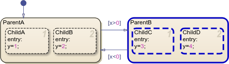
On each time step, the chart executes actions and evaluates transitions for each parallel state in a level of hierarchy in sequential order, which is indicated by the number in the upper-right corner of each state. For instance, when ParentB becomes active, the chart enters both ChildC and ChildD. Because ChildC has an execution order of 1, it sets y to 3. Then, on the same time step, ChildD overwrites y to 4.
You can change the execution order by right-clicking a state, clicking Execution Order, and selecting a new order.
In this example, you use parallel states to finish an incomplete model of a battery system. The battery system contains two independent components:
A rechargeable main battery
A non-rechargeable emergency battery that maintains essential functions if the main battery becomes empty
Open Model
The sfGetStartedParallel model represents the control logic for a rechargeable battery system. To build the model, follow the instructions in the previous steps of the tutorial.
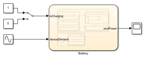
Double-click the Chart block to enter the battery chart.
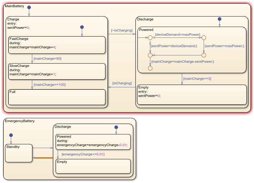
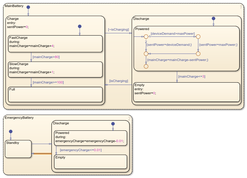
The chart contains two non-parallel states that represent the main and emergency batteries. Each battery contains nested child states that represent operating modes for charging, discharging, or standing by. Additionally, the batteries use input, output, and local data:
isCharging: An input data that represents whether the battery system is connected to a power source. It determines the active state of the main battery.deviceDemand: An input data that represents the power demand of the connected device.maxWatts: A local data the represents the maximum power output of the main battery.sentPower: A local data that represents the output wattage of the main battery. IfdeviceDemandis less thanmaxWatts, it equalsdeviceDemand. Otherwise, it equalsmaxWatts.mainChargeandemergencyCharge: Local data that represent the charge of each battery as a percent.
For details on the operation of the main battery, see the previous steps in the tutorial.
Enable Parallel Decomposition
You can enable parallel execution for child states by right-clicking the parent component and selecting Decomposition > Parallel.
Because the MainBattery and EmergencyBattery states do not have a parent state, the chart is considered the parent. Enable parallel decomposition for the chart by right-clicking an empty section of canvas and selecting Decomposition > Parallel. The borders of the two charts become dashed, which indicates they are parallel states.
Broadcast and Receive Events
In Stateflow® charts, you can enable a component to trigger behavior in other components of the chart or model by broadcasting events. For instance, in a chart with two parallel states, you can broadcast an event in one state to cause a transition in the other.
To broadcast an event from a state or transition, use the send operator using the format:
send(event_name,receiving_state)
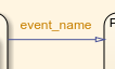
To receive the event broadcast in a transition, enter the name of the event in the transition label. The event does not require brackets or braces. The transition must be a direct or indirect child of the receiving state.
The original project requirements for the battery system state that the emergency battery should discharge when the main battery becomes empty and move to standby when the main battery begins charging. Toggle the operating mode of the emergency battery by broadcasting events from the main battery.
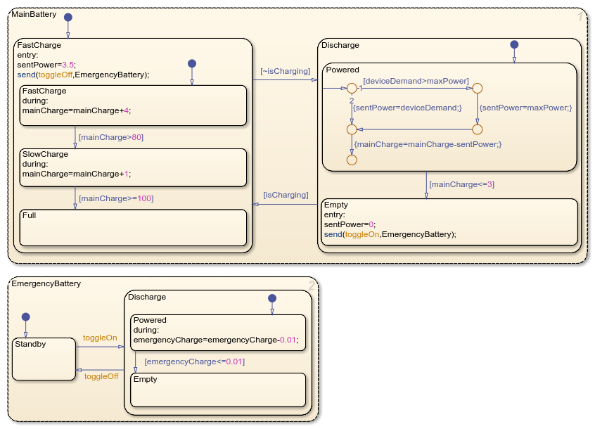
1. In the state MainBattery, in the entry action of the child state Empty, broadcast an event called toggleOn to the state EmergencyBattery:
entry:
sentPower=0;
send(toggleOn,EmergencyBattery);
2. In the state MainBattery, in the entry action of the child state Charge, broadcast an event called toggleOff to the state EmergencyBattery:
entry:
sentPower=3.5;
send(toggleOff,EmergencyBattery);
3. In the state EmergencyBattery, double-click the transition from Standby to Discharge and enter the label toggleOn.
4. Double-click the transition from Discharge to Standby and enter the label toggleOff.
5. In the Symbols pane, click the Resolve undefined symbols button to define toggleOn and toggleOff as local events. In the entry actions and transitions, toggleOn and toggleOff become orange, which indicates an event.
Simulate Model
The model logs two values to the Simulation Data Inspector:
The activity of the
Emptystate inMainBattery, where1is active and0is inactive.The name of the active child state of
EmergencyBattery.
Simulate the model and observe these values.
Return to the top-level Simulink model. The Manual Switch block changes the operating mode of the main battery. When the value is
1, the battery charges. When the value is0, the battery discharges.To simulate the model, in the Simulation tab, click Run. The Chart block shows the execution of the chart.
Double-click the Manual Switch block to discharge the battery. After a few seconds, when the main battery transitions to
Empty, double-click the Manual Switch block to charge the battery. Repeat this process several times.To stop the simulation, in the Simulation tab, click Stop.
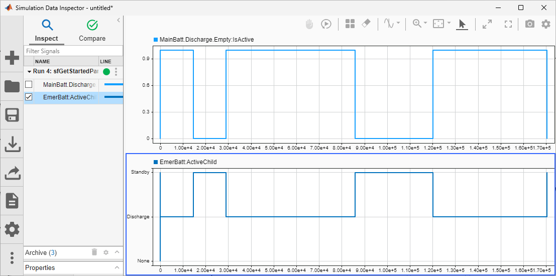
To open the Simulation Data Inspector, in the Simulation tab, click Data Inspector.
To show the activity of the
Emptystate, in the Inspect tab, clickMainBattery.Discharge.Empty:IsActive.To show the active child state of the
EmergencyBatterystate, in the Inspect tab, clickEmergencyBattery:ActiveChild.
When the main battery is empty, the emergency battery discharges. When the main battery leaves the Empty state and begins charging, the emergency battery moves to standby.