Sense Stepper Motor Angle Using Hall-Effect Encoder
This example shows how to detect the angle of a stepper motor using a Hall-Effect Rotary Encoder block.
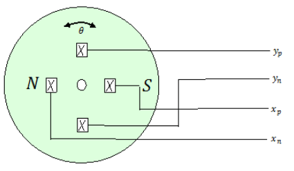
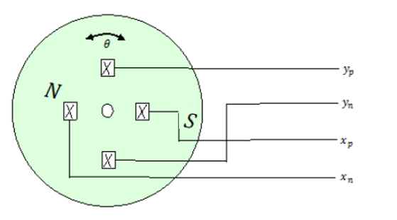
The Hall-Effect Rotary Encoder block models a 360° rotary position sensor using four Hall elements spaced equally under a rotating magnet. Each Hall element varies its output voltage based on the strength of the applied magnetic field. The Hall elements align with the poles of the rotating magnet and experience maximal magnetic flux density at different orientations because the elements are spaced 90° apart. The elements therefore generate four sinusoidal waveforms corresponding to their output Hall voltages, 90° out of phase with one another. These four waveforms uniquely encode the 360° rotary position.
This example uses two models of a stepper motor driven up from 0° to 360°, and then down from 360° to 0°:
In the
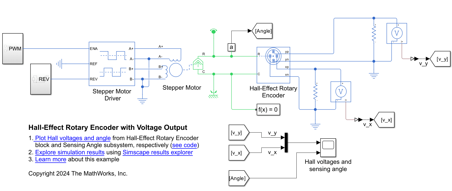
HallEffectRotaryEncoderVoltagemodel, the Hall-Effect Rotary Encoder block has conserving ports in the electrical domain. These ports output the raw Hall element voltages. To enable these electrical conserving ports, set the Output interface parameter toElectrical connections.In the
HallEffectRotaryEncoderAnglemodel, the Hall-Effect Rotary Encoder block has a physical signal output port, Angle. To enable this port, set the Output interface parameter toDecoded Angular Position.
Open Hall-Effect Rotary Encoder with Voltage Output Model
Open the HallEffectRotaryEncoderVoltage model.
open_system("HallEffectRotaryEncoderVoltage.slx")
sim("HallEffectRotaryEncoderVoltage.slx")
Plot Simulation Results from Simscape Logging
The HallEffectRotaryEncoderVoltage model shows how the Hall-Effect sensor detects distinct components of the rotational position signal through changes in magnetic flux density. This figure shows a schematic of the encoder. The hall elements, , , , and , remain in a fixed position. The north and south poles of the magnet rotate at the motor shaft angle θ.
Simulate the model and plot the results.
HallEffectPlotVoltagesAndAngle
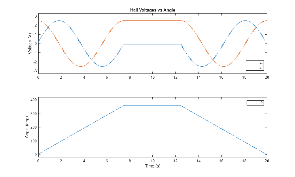
The voltages follow a sinusoidal path with respect to the angle when the motor steps up and steps down. The maxima and minima voltages occur when the poles of the magnet align with two of the sensors. At the start of the simulation, the magnetic poles align with the and sensors. This alignment creates a maximum voltage across the xn and xp ports, Vx, and a zero voltage across the yn and yp ports, Vy. When the shaft starts to rotate, Vx decreases and Vy increases as the north pole moves toward the sensor and the south pole moves toward the sensor.
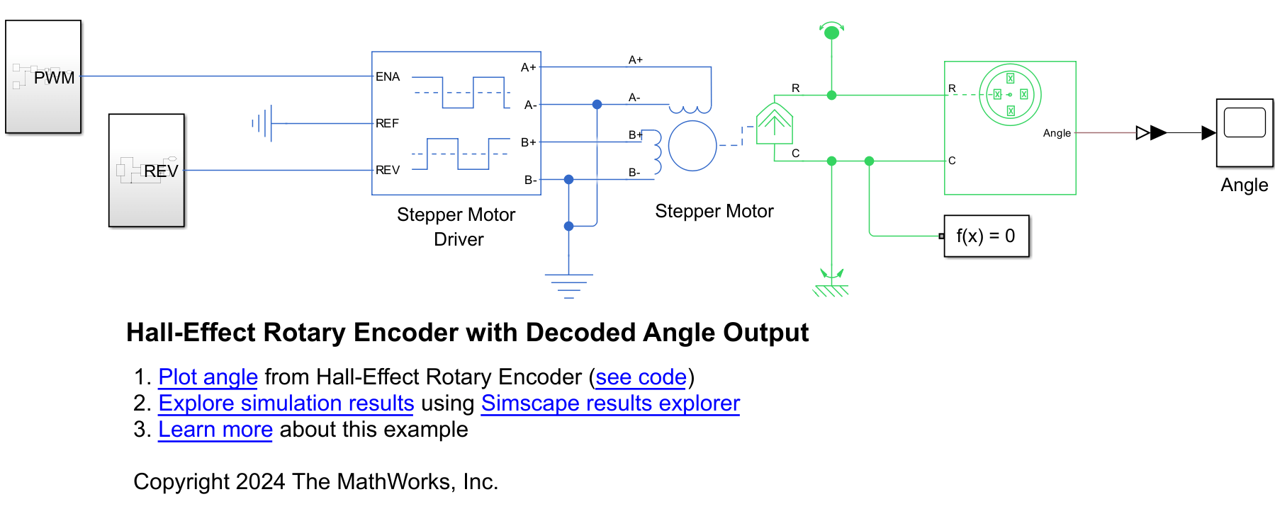
Open Hall-Effect Rotary Encoder with Decoded Angle Output Model
Open the HallEffectRotaryEncoderAngle model.
open_system("HallEffectRotaryEncoderAngle.slx")
sim("HallEffectRotaryEncoderAngle.slx")
Plot Simulation Results from Simscape Logging
The HallEffectRotaryEncoderAngle model shows how to calculate the angle of the stepper motor using the Angle port of the Hall-Effect Rotary Encoder block. Simulate the model and plot the results.
HallEffectPlotAngle
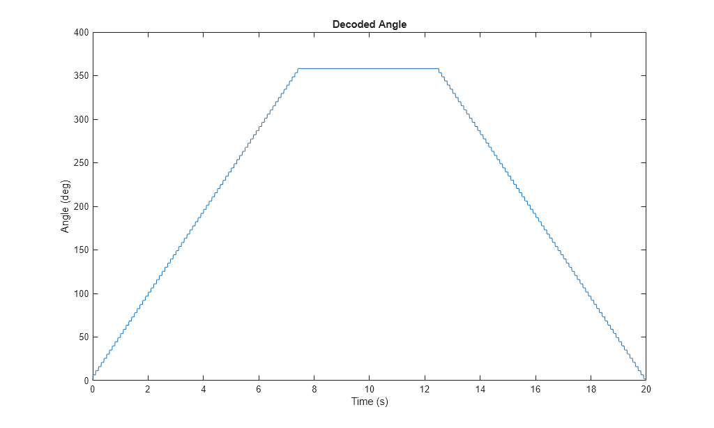
The results match those of the HallEffectRotaryEncoderVoltage model.