IEEE 39-Bus System
This example shows how to model a 39-bus three-phase power system network. This example is based on the IEEE benchmark test case. For more information, see "IEEE PES Task Force on Benchmark Systems for Stability Controls" by Hiskens [1].
Model Overview
The IEEE39BusSystem model comprises four subsystems:
Generators- Comprises ten generators and associated automatic voltage regulators (AVR), exciters, power system stabilizers (PSS), governors, and prime moversGrid- Models the power system network by using transmission line, transformer, and busbar blocksLoads- Represents all the loads of the networkMeasurements- Measures the terminal voltages and rotor speeds of the generators
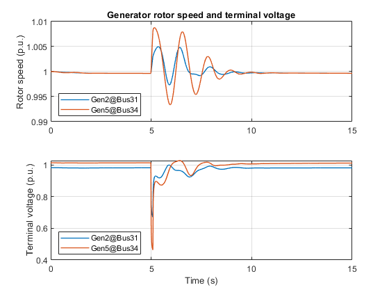
Simscape™ Electrical™ first performs a load-flow analysis for the model and determines the steady-state operating point for a given loading condition. The simulation then starts from this steady-state operating point. At time 5 s, a three-phase-to-ground fault occurs at Bus-16. The fault then clears in 0.1 s. After the simulation, the software adds an annotation that shows the resulting load-flow solution to each busbar in the model.

Plot Simulation Results from Simscape Logging
This plot shows the rotor speed and terminal voltage of Generator-2 at the Bus-31 swing bus and Generator-5 at the Bus-34 PV bus.

References
[1] Hiskens, Ian. "IEEE PES Task Force on Benchmark Systems for Stability Controls." Nov. 19, 2013
See Also
Perform a Load-Flow Analysis Using Simscape Electrical