Model High-Voltage Direct-Current Transmission Using Modular Multilevel Converters
This example models a high-voltage, direct-current (HVDC) transmission system using modular multilevel converters (MMC).
Open Model
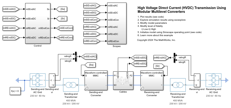
The MMC-HVDC transmission system comprises the power sending end, power receiving end, and DC transmission line. Each end includes the AC grid, transformer, smoothing reactor, and modular multilevel converter.
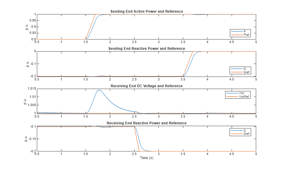
Initially, at the power sending end, the converter controls an active power of 0.8 p.u., or 320 MW, to flow out from the AC grid. The converter also controls a reactive power of 0.2 p.u., or 80 MVAr, to flow into the AC grid. At the power receiving end, the converter regulates the DC voltage at 1 p.u., or 400 kV, and controls a reactive power of 0.1 p.u., or 40 MVAr, to flow into the AC grid. At a simulation time of 1.5 s, the sending end increases the active power from 0.8 p.u. to 1 p.u. At a simulation time of 2.5 s, the receiving-end converter controls a reactive power of 0.2 p.u., or 80 MVAr, to flow into the AC grid. At a simulation time of 3.5 s, the sending-end converter controls a reactive power of 0 p.u. to flow into the AC grid.

Model Fidelity Levels Using Variant Controls
Use the ModularMultilevelConverterHVDCTransParameters script to create variant controls for the modular multilevel converter. Specifically, this script defines the WaveformControlledMMC and PWMControlledMMC Simulink.Variant objects. Use these objects with the average-value and equivalent-switching modular multilevel converter. This script also defines a fidelity variable that specifies the level of fidelity. This example supports two different levels of fidelity:
Low - An average-value modular multilevel converter models the converter.
High - An equivalent-switching modular multilevel converter models the converter.
To specify the level of fidelity, use the ModularMultilevelConverterHVDCTransVariantControl script. This script configures the sampling time accordingly.
Initialize Model Using Simscape Operating Point
In this example, you create a Simscape™ OperatingPoint object from the logged simulation data and then use this operating point to initialize the model for a subsequent simulation run.
Use the ModularMultilevelConverterHVDCTransInitializeModel script to perform these steps:
Configure the model based on the fidelity level.
Simulate the model until it reaches a steady-state operation point at 1 second, then create an operating point from the logged simulation data.
Calculate the initial conditions used in the
Controlsubsystem from the operating point.
Plot Simulation Results from Simscape Logging
These plots show the active and reactive power of the sending end and the DC voltage and reactive power of the receiving end.

See Also
DC Cable | Modular Multilevel Converter Arm