Design, Operate, and Control Remote Microgrid
This example shows how to develop, evaluate, and operate a remote microgrid. You also evaluate the microgrid and controller operations against various standards, including IEEE® Std 2030.9-2019, IEC TS 62898-1:2017 and IEEE Std 2030.7-2017. The planning objectives in the design of the remote microgrid include power reliability, renewable power usage, and reduction in diesel consumption. The key indices for economic benefits for the remote microgrid include life-cycle cost, net revenue, payback period, and internal rate of return. You can download this model in MATLAB® or access it from MATLAB Central File Exchange and GitHub®.
Example Overview
In this example, you learn how to:
Design a remote microgrid that complies with IEEE standards for power reliability, maximizes renewable power usage, and reduces diesel consumption.
Simulate different operating scenarios, including a feeder switch in secondary substation, diesel trip, diesel planned islanding, and diesel start and resynchronization.
Verify the compliance of the designed microgrid by comparing the system performance against the IEEE standards.
Evaluate the system performance, system design, and reduction in diesel usage with three performance indices.
This figure shows the relationship between various aspects of the remote microgrid and the different standards in this example.

For more information, follow these steps to explore the overview that opens in your web browser or see Microgrid Design with Simscape.
Download Files
Clone the up-to-date repository in the current folder using the gitclone function.
gitclone("https://github.com/simscape/Microgrid-Simscape");Alternatively, you can download the latest files using these options.
Download ZIP files of this project from Microgrid Design with Simscape (MATLAB Central File Exchange).
Clone the Git™ repository from Microgrid Design with Simscape (GitHub).
Open Project
After you use the gitclone function, MATLAB creates a new folder in the current folder. This example uses projects to manage the supporting files. Open the MicrogridDesignWithSimscape project file. If you have any projects open, MATLAB closes them before loading this project. Configuring the project environment takes several minutes because the model has hundreds of supporting files. Click the Learn More hyperlink on the top-level model canvas to open an overview that helps you explore the subsystems and the construction of the model. The overview also shows you the main simulation results.
openProject("Microgrid-Simscape");Explore Project
Remote Microgrid System
The top-level model shows the design of the microgrid in this example. The microgrid comprises:
Power generation sources for diesel generation and photovoltaic generation
A battery energy storage system (BESS)
A medium-voltage (MV) load and a low-voltage (LV) load
A substation with two outgoing feeders
A microgrid controller at the substation
The Diesel Substation, BESS, & Microgrid Controller subsystem includes the model of the diesel generator and the BESS. This subsystem also connects the diesel generator to the microgrid at the point of common coupling (PCC). Two outgoing MV feeders from the substation connect the microgrid assets. The MV load and the PV subsystem connect to the Feeder 1 while the LV load connect to the Feeder 2 through the secondary substation. The Operator Control Room subsystem collects all the setpoints and measurements.

Diesel Substation, BESS, and Microgrid Controller System
Look under the mask of the Diesel Substation, BESS, & Microgrid Controller subsystem. This subsystem connects the diesel generator to the microgrid through the transformer and disconnectors. The PCC Measurements and PCC Breaker subsystem models the measurements at the PCC. The BESS and Controller subsystem comprises the battery modules and the grid-side converter, filter, measurement system, and control system. The Microgrid Controller subsystem implements the microgrid controller functions.

BESS and Controller System
Inside the Diesel Substation, BESS, & Microgrid Controller subsystem, look under the mask of the Bess and Controller subsystem. The BESS subsystem implements the BESS module and the BESS converter. The converter connects the battery modules to the grid and controls the power flow through the converter. The BESS Control subsystem regulates the voltage and the frequency based on the voltage and frequency references it receives from the microgrid controller. The BESS Output Filter and Transformer subsystem models the BESS filter and transformer. The BESS Converter Measurement subsystem measures the BESS output power, voltage, and current.

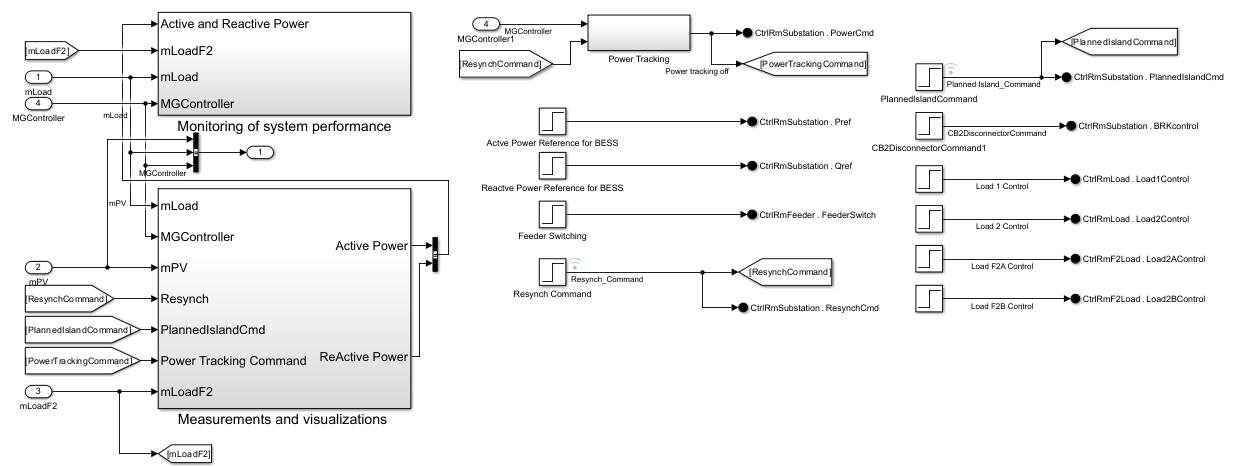
Operator Control Room System
The Operator Control Room subsystem collects all the setpoints and commands. It also gathers the measured quantities and the system performance analysis.
Performance of Microgrid After Feeder Switch in Secondary Substation
Initialize the parameters and run the model. At the MATLAB Command Window, run:
caseNum = 1;
remoteMicrogridInputData;
remoteMicrogrid;
This plot shows the three-phase voltage and current output of the BESS and the diesel current. At 3 seconds, the upper feeder disconnects and the lower feeder connects to the LV load. At 6 seconds, part of the LV load disconnects as well. The stable voltage output and current output from the BESS verify a stable control during the switching process. At the MATLAB Command Window, run:
remoteMicrogridPlotBESSVI;

This plot shows the active and reactive power of BESS, diesel, PV, and loads. The stable active power output and reactive power output verify the efficacy of the control methods and microgrid operations. At the MATLAB Command Window, run:
remoteMicrogridPlotPQ;

This plot shows the voltage and current at the loads. The load voltage and load current remain steady during feeder switch and LV load disconnection. At the MATLAB Command Window, run:
remoteMicrogridPlotLoadVIRMS;

To find the latest examples from the MathWorks Simscape Team, see MathWorks Simscape Team on MATLAB Central.