Bidirectional DC-DC Converter Current Control
This example shows how to control the inductor current of a Bidirectional DC-DC Converter. To adjust the duty cycle, the Control subsystem uses a PI-based control algorithm. The Bidirectional DC-DC Converter uses averaged switches. To achieve different levels of fidelity, you can use either modulation waveforms, averaged gate pulses, or gate pulses.
Model

Simulation Results from Simscape Logging
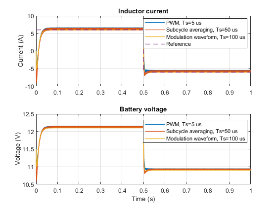
The plot below shows the requested and measured inductor current for the test and the battery voltage in the 12V network.

Results from Real-Time Simulation
This example, with Bidirectional DC-DC Converter controlled using modulation waveform, has been tested on these platforms:
Speedgoat™ Performance real-time target machine with an Intel® 3.5 GHz i7 multi-core CPU and 4 GB RAM.
dSPACE® SCALEXIO LabBox with Intel® Core XEON E3-1275v3 at 3.5GHz and 4 GB RAM.
You can run this model in real time with a step size of 20 microseconds by using the Simscape local solver. For small sample rates, a task overrun might occur during the initial task execution due to a cold cache. To avoid this overrun, if the selected platform supports these options, relax the start-up behavior by specifying a limited number of task overruns or increasing the sample time of periodic tasks during the start-up phase of the real-time application.
See Also
Bidirectional DC-DC Converter | Two-Pulse Gate Multiplexer | Battery