Average-Value DC-DC Converter Control
This example shows how to control the output voltage of a buck-boost converter. To adjust the duty cycle, the Control subsystem uses a PI-based control algorithm. An average-value DC-DC converter model is used to speed up the simulation. The input voltage and the system load are held constant throughout the simulation. The total simulation time (t) is 0.25 s. At t = 0.15 s, the voltage reference changes and the system switches from buck mode to boost mode.
Model

Simulation Results from Simscape Logging
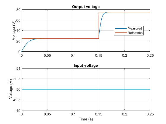
The plot below shows the requested and measured voltage for the test and the input voltage in the circuit.
Results from Real-Time Simulation
This example has been tested on these platforms:
Speedgoat™ Performance real-time target machine with an Intel® 3.5 GHz i7 multi-core CPU and 4 GB RAM.
dSPACE® SCALEXIO LabBox with Intel® Core XEON E3-1275v3 at 3.5GHz and 4 GB RAM.
You can run this model in real time with a step size of 10 microseconds by using the Simscape local solver. For small sample rates, a task overrun might occur during the initial task execution due to a cold cache. To avoid this overrun, if the selected platform supports these options, relax the start-up behavior by specifying a limited number of task overruns or increasing the sample time of periodic tasks during the start-up phase of the real-time application.