Main Content

Load Flow Source

Three-phase voltage source for performing load flow analysis

  • Load Flow Source block

Libraries:
Simscape / Electrical / Sources

Description

The Load Flow Source block is a three-phase voltage source that you use for a load-flow analysis. This block is only for three-phase Simscape™ networks that are compatible with frequency-time simulation mode.

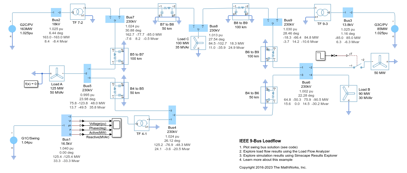
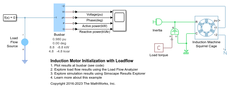
The block can be used with the Busbar block to implement a swing bus, PV bus, or PQ bus. The type of bus is selected from the Source type drop-down menu parameter. See Perform a Load-Flow Analysis Using Simscape Electrical for more information about load flow in Simscape Electrical™.

When you select None for the Source impedance parameter, the Load Flow Source block models an ideal three-phase voltage source that maintains sinusoidal voltage of the specified magnitude across its terminals, independently of the current flowing through the source.

The source has a wye configuration, and port n provides a connection to the center of the wye. Port ~ is a three-phase port that represents the phases a, b, and c. The current is positive if it flows from positive to the center of the wye, and the voltage across each phase is equal to the difference between the voltage at the positive terminal and the center of the wye, V(+) – Vn.

Variables

To set the priority and initial target values for the block variables before simulation, use the Initial Targets section in the block dialog box or Property Inspector. For more information, see Set Priority and Initial Target for Block Variables.

Nominal values provide a way to specify the expected magnitude of a variable in a model. Using system scaling based on nominal values increases the simulation robustness. You can specify nominal values using different sources, including the Nominal Values section in the block dialog box or Property Inspector. For more information, see System Scaling by Nominal Values.

Examples

Limitations

  • If you do not initialize or simulate by using frequency-time equations, the Source type parameter must be set to Voltage source with series impedance.

  • When initializing the block when Source type is set to swing bus, PV bus or PQ bus, including the internal impedance can result in initialization convergence issues. Resolve the convergence issues by using the Internal source phase search range parameter, omitting the impedance, or modelling the impedance external to the Load Flow Source block.

Ports

Conserving

expand all

Three-phase port associated with the voltage phases a, b, and c.

Electrical conserving port associated with the center of the wye.

Parameters

expand all

Main

Type of voltage source that the block models.

Dependencies

The visibility of Source voltage (pu), Terminal voltage (pu), Active power generated, Active power consumed, Reactive power consumed, Source phase, Minimum voltage (pu) and Internal source phase search range depend on the value that you choose for this parameter.

Per-unit voltage that the source generates.

Dependencies

This parameter is visible only when you set the Source type parameter to Voltage source with series impedance.

Per-unit terminal voltage that the source generates.

Dependencies

This parameter is visible only if you set the Source type parameter to Swing bus or PV bus.

Active power that the source generates.

Dependencies

This parameter is visible only if you set the Source type parameter to PV bus.

Active power that the source consumes.

Dependencies

This parameter is visible only if you set the Source type parameter to PQ bus.

Reactive power that the source consumes.

Dependencies

This parameter is visible only if you set the Source type parameter to PQ bus.

Rated phase-to-phase root mean square (RMS) voltage.

Rated frequency, in Hz.

Phase shift of the source.

Dependencies

This parameter is visible only if you set the Source type parameter to Voltage source with series impedance.

Impedance

Type of source impedance. Selecting any other options enables other parameters. The options are:

  • None

  • X/R Ratio

  • Series R

  • Series L

  • Series RL

Dependencies

The visibility of Short-circuit power level, Source X/R ratio, Source impedance parasitic parallel conductance, Source resistance, and Source inductance depend on the value that you choose for this parameter.

Short-circuit power level.

Dependencies

This parameter is visible only if you set the Source impedance parameter to X/R ratio.

Reactance-to-resistance ratio.

Dependencies

This parameter is visible only if you set the Source impedance parameter to X/R ratio.

Source impedance parasitic parallel conductance.

Dependencies

This parameter is visible only if you set the Source impedance parameter to X/R ratio or Series L or Series RL.

Source resistance.

Dependencies

This parameter is visible only if you set the Source impedance parameter to Series R or Series RL.

Source inductance.

Dependencies

This parameter is visible only if you set the Source impedance parameter to Series L or Series RL.

Expected Ranges

Per-unit minimum voltage. This parameter assists with the initial solve in models with non-physical, very low voltages.

Dependencies

This parameter is visible only if you set the Source type parameter in the Main setting to Swing bus, PV bus or PQ bus.

Vector of the lower and upper boundaries for the internal source phase search. Use this range to help the initial solve converge to the desired load flow solution.

Dependencies

This parameter is visible only if, in the Main setting, you set the Source type parameter to PV bus or PQ bus.

Extended Capabilities

C/C++ Code Generation
Generate C and C++ code using Simulink® Coder™.

Version History

Introduced in R2019b