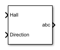
BLDC Commutation Logic
Switch-commutation logic for brushless DC motors
Libraries:
Simscape /
Electrical /
Control /
BLDC Control
Description
The BLDC Commutation Logic block implements a commutation logic for brushless DC motors as part of this control algorithm.

The commutation logic is based on the Hall signals as summarized in this table.
| Hall Sensors | Motor Phases | ||||
|---|---|---|---|---|---|
| Hall a | Hall b | Hall c | Phase a | Phase b | Phase c |
| 0 | 0 | 0 | 0 | 0 | 0 |
| 1 | 1 | 0 | 0 | 1 | -1 |
| 0 | 1 | 0 | -1 | 1 | 0 |
| 0 | 1 | 1 | -1 | 0 | 1 |
| 0 | 0 | 1 | 0 | -1 | 1 |
| 1 | 0 | 1 | 1 | -1 | 0 |
| 1 | 0 | 0 | 1 | 0 | -1 |
| 1 | 1 | 1 | 0 | 0 | 0 |
Examples
Ports
Input
Output
Parameters
References
[1] Stirban, A., I. Boldea, and G. D. Andreescu. "Motion-Sensorless Control of BLDC-PM Motor With Offline FEM-Information-Assisted Position and Speed Observer." IEEE Transactions on Industry Applications. 48, no. 6 (2012): 1950-1958.
Extended Capabilities
Version History
Introduced in R2018a

