Modeling Bodies
Bodies are the basic constituents of a multibody model. They are the solid components that you connect when assembling a model and the subjects upon which all forces and torques in that model ultimately act. The planets and the sun serve as bodies in a model of the solar system, for example, and wings do too in a model of a flapping mechanism.
A Flapping Mechanism as an Assembly of Bodies

If you are familiar with CAD modeling, you can loosely think of bodies as equivalents of CAD parts, each a modular component with geometry and material. The modeling approach may differ—for example, there are no sketches to draw—but, conceptually, the end result is the same: something that you can connect, constrain, act upon, and visualize.
Body Elements
A body is a collection of simpler body elements: solids with geometry and inertia and, less often, plain inertias (without assigned geometries) and plain geometries (without associated inertias). The body elements that you model and the ways in which you connect them determine the overall attributes of the body.
Bodies with simple shapes often require a single solid. Those with complex shapes or inertias may require several solids and the occasional plain inertia or plain geometry. Like bricks in a modular build set, the properties of the various body elements can differ from each other. It is up to you to combine them in a way that produces the desired body.
A Wing Body as a Collection of Solids

Each body element comprises one or more frames and a set of material attributes. The frames determine the placement of the body elements relative to each other and provide the attachment points for joints and constraints. The attributes factor in the dynamic behavior of the body elements and, in those with geometry, help determine their visual appearance.
Frames on a Wing Body

Material Attributes
The attributes of solids include inertia and color. Geometry enables the automatic calculation of inertia parameters and, in conjunction with color, visualization. Inertia quantifies the resistance to changes in motion and factor into the calculation of the forces and torques required to induce an acceleration.
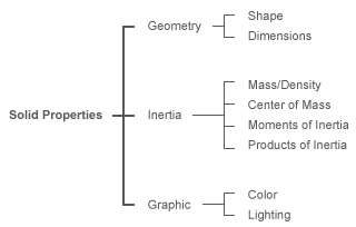
The attributes of other body elements are more limited in scope. Those of plain inertias include only inertia, with parameters that in the general case encompass mass, center of mass, moments of inertia, and products of inertia.
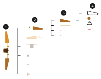
The figure summarizes the structure of a typical body (here a wing) in the context of a typical multibody model (here a flapping wing mechanism). Multibody assemblies (1) comprise bodies (2), bodies comprise body elements (3)—often all solids—and body elements comprise frames and any material attributes relevant to them (4).
Relevant Blocks
You can model most bodies using the solid blocks and Rigid Transform block. The solid blocks represent their namesake—a solid element of a certain type. The block parameters set the attributes of the solid and a frame port, labeled R, provides a reference frame for connection to a model. You can create additional, custom, frames and position them using a variety of solid features.
The Rigid Transform block represents a fixed spatial relationship between two frames. Whenever you add a Rigid Transform block to a frame connection line, you replace the coincidence relationship originally set by that line with a rotational and translational offset that you specify in the block dialog box.
Only rarely do bodies contain other blocks. Those that remain in the Body Elements library—Graphic, Inertia, and all in the Variable Mass sublibrary—serve special cases. Use them, for example, to add graphic markers, adjust inertia through compounding, or allow inertia to vary during simulation.
Body Visualization
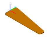
You can visualize individual solids and complete models. The right visualization tool to use depends on which of the two you want to visualize. You can visualize individual solids directly through their respective solid blocks. In its dialog box, The solid blocks provide a visualization pane that shows the geometry, frames, and color of the solid that it represents. The visualization works even if the block diagram is incomplete or invalid.
A Typical Solid Visualization
You can visualize a model, and all the bodies within it, using the Simscape Multibody visualization utility, Multibody Explorer. The model must be free of kinematic conflicts, such as those due to mutually incompatible joints and constraints. It must also contain one Solver Configuration block for every topologically distinct multibody network—each a group of Simscape Multibody blocks that connect without breaks in their frame connection lines.
Multibody Explorer opens a static model visualization in its initial configuration whenever you do a diagram update (in the Debug tab, click Update Model). The initial configuration is the aggregate result of all initial joint positions and angles, whose values you can specify using joint state targets. The visualization becomes dynamic when you run a simulation, although this is a task you are unlikely to perform while still modeling bodies.
A Typical Model Visualization

For more information about visualization, see Visualize a Model and Its Components.
A Typical Body
At the MATLAB® command prompt, enter
openExample("sm/PointOnCurveExample"). A model of a
flapping wing mechanism opens up. Look inside the mask of the subsystem block
named RightWing. You can do this by clicking the down arrow
at the bottom left corner of the block. The blocks inside the subsystem are a
typical representation of a body.

The solid blocks each represent a section of the wing body. The frame connection lines between the solid blocks, and the Rigid Transform blocks that some of the connection lines contain, define the spatial relationships that exist between the solid sections. Open the dialog box of the Cylindrical Solid block named CrossPin and explore its attributes:
The Geometry parameters are by default expanded. The Cylindrical Solid block uses a shape with its relevant dimensions (Radius, Length) parameterized in terms of MATLAB variables (
Rp,Lp). All variables are defined numerically in the subsystem mask.
Expand the Inertia parameters. The block is configured to calculate the bulk of the inertia parameters from geometry and a mass parameter (Density). This parameter too is parameterized in terms of a MATLAB variable (
rho).
Expand the Graphic parameters. The block uses a
Simplecolor model with the visual properties of the solid (Color, Opacity) parameterized in terms of MATLAB variables (lclr) or specified numerically (1.0).
In the visualization toolstrip, click the frame button. The visualization pane shows the frames associated with the solid. This solid has a single frame, the local reference frame that by default every solid block has. The placement of this frame relative to the geometry impacts the placement of the geometry in the context of the model.

Update the block diagram. Multibody Explorer opens with a static visualization of the flapping wing model in its initial configuration. In the tree view pane (located on the left side of Multibody Explorer), right-click the RightWing node and select
Show Only This. The visualization pane updates to show only the body elements that compose the selected component.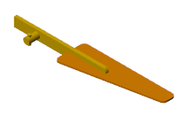
Boundaries of Bodies
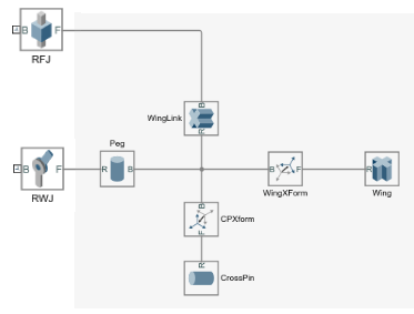
Direct connection lines and Rigid Transform blocks unite body elements into a single body. Such connections are treated as internal to the bodies they belong to. Joint and constraint blocks in turn separate solids into different bodies. These blocks identify the boundaries of the bodies that they connect. This distinction has practical consequences in models with Gravitational Field blocks.
The figure shows a flattened portion of the PointOnCurveExample block
diagram. The joint blocks named RFJ and
RWJ separate the blocks that compose the body to their
right (identified by the shaded area) from the neighboring bodies to which it
connects (not shown).
Impact on Gravitational Fields
By design, the Gravitational Field block exerts a force on the center of mass of a body. The center of mass is determined from the aggregate of all Body Elements blocks that comprise the body. If two solid blocks connect through a Rigid Transform block, they belong to the same body. A single gravitational force then acts at the center of mass of that body.
If, however, the Cylindrical Solid blocks connect through a Revolute Joint block, they belong to separate bodies. Two gravitational forces then apply at the individual centers of mass of those bodies. The same is true even if you replace the Revolute Joint block with a Weld Joint block. Regardless of its type, every joint block separates the body elements that it connects into separate bodies.
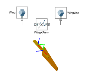
The figure shows the effect of adding a Weld Joint block to a block network that originally composed a single body. This joint block divides the body into two bodies, one comprising only the Cylindrical Solid block named WingLink, the other comprising the remaining Cylindrical Solid and Rigid Transform blocks. Gravitational Field blocks in your model, if any, would in this case exert a force at the calculated center of mass of each body.

A Note on Rigid Loops
The blocks that comprise a body connect rigidly and, in the ideal case, in series. The result is a tree structure in which the path between any two frames is unique. It is technically possible, however, to rigidly connect blocks so that they form a rigid loop, a closed structure formed by connecting the open ends of a branch or tree.
A Rigid Transform Loop
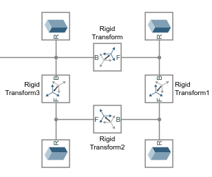
Rigid transform loops are disallowed in a model. They contain redundant (and unnecessary) rigid connections and these could lead to preventable numerical errors if included in a model. If your model contains a rigid kinematic loop, you must break that loop by removing of its redundant rigid connections. The figure shows an example.

Bodies as Simulink Subsystems
It is common practice to enclose the blocks that belong to a body inside a Simulink Subsystem block. You can save the resulting Subsystem block in a Simulink® library for later use in different models. The mask of the Subsystem block provides a place to define the variables and parameters that are common to the enclosed blocks—often some length, density, and color—without cluttering the workspace of a model.
You can model a body and convert it to a Simulink subsystem at any time prior to its use in a multibody model. For example, when modeling a piston engine, you can defer work on a piston body until you are ready to connect the piston to the engine housing or to the connecting rod. However, given that the shape and size of one body often depend on those of another, you should at least consider those attributes prior to focusing on assembly.
A Typical Body Subsystem
At the MATLAB command prompt, enter
openExample("sm/PointOnCurveLibrary"). A Simulink library opens with subsystem blocks representing two of the
bodies used in the PointOnCurveExample model. Each of the
blocks has frame ports for connection to a model.

Double-click the subsystem block named Peg. A custom
dialog box opens with the key parameters required to completely define this
body. The values specified here are used in the Cylindrical
Solid and Rigid Transform
blocks that compose the subsystem block.
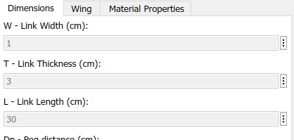
Right-click the subsystem block and select Mask > View Mask. The Simulink Mask Editor opens with the parameters and code relevant to the wing body. The parameters and the MATLAB variables associated with them are defined in the Parameters & Dialog tab. The code used to generate the wing and spar shape profiles is defined in the Initialization tab.

Right-click the subsystem block and select Mask > Look Under Mask. The block diagram corresponding to this subsystem opens up. Open the dialog boxes of some of the blocks and note the MATLAB variables used to define many of their parameters. These are the variables defined in the subsystem mask and specified in the subsystem block dialog box.
