Propagate Variant Conditions to Define Variant Regions Outside Variant Subsystems to Promote Consistency and Reduce Errors
Simulink® propagates variant conditions from Variant Subsystem blocks to their connecting blocks. The propagation of variant conditions enables Simulink to determine which components of the model remain active during simulation. Simulink then deactivates the model components associated with the inactive choices and highlights the active connections. By default, variant conditions do not propagate outside the Variant Subsystem block. To allow variant conditions to propagate to the connecting blocks, select the Propagate conditions outside of variant subsystem parameter on the Variant Subsystem block. For more information about the Variant Subsystem block, see Variant Subsystem.
Simulink propagates variant conditions from the Variant Subsystem blocks
to their connecting blocks, allowing other parts of the model, such as subsystems, blocks, and
functions, to use the same variant conditions. Propagating variant conditions outside of a
Variant Subsystem block promotes consistent behavior throughout the model.
The automatic propagation of variant conditions eliminates the need for manual synchronization
between different blocks, preventing discrepancies that could arise from inconsistent
condition handling. When the variant choices within a Variant Subsystem block
have different numbers of input and output ports, it is recommended that you set the
Propagate conditions outside of variant subsystem parameter to
on. This setting enables the rest of the model to adapt to the interface
of active variant choice, preventing interface mismatches. Conversely, when all variant
choices have identical interfaces, connections to and from the Variant Subsystem block remain
consistent regardless of which variant is active. In this case, setting Propagate
conditions outside of variant subsystem to off can improve
simulation performance, as the model does not need to adapt to changes within the
Variant Subsystem block.
Tip
Variant condition annotations on model components help you visualize the propagated conditions. To view the annotations, on the Debug tab, select Information Overlays > Variant Legend. If Variant Legend is not available, on the Debug tab, select Information Overlays > Variant Conditions. For more information, see Visualize Propagated Variant Conditions in Variant Conditions Legend.
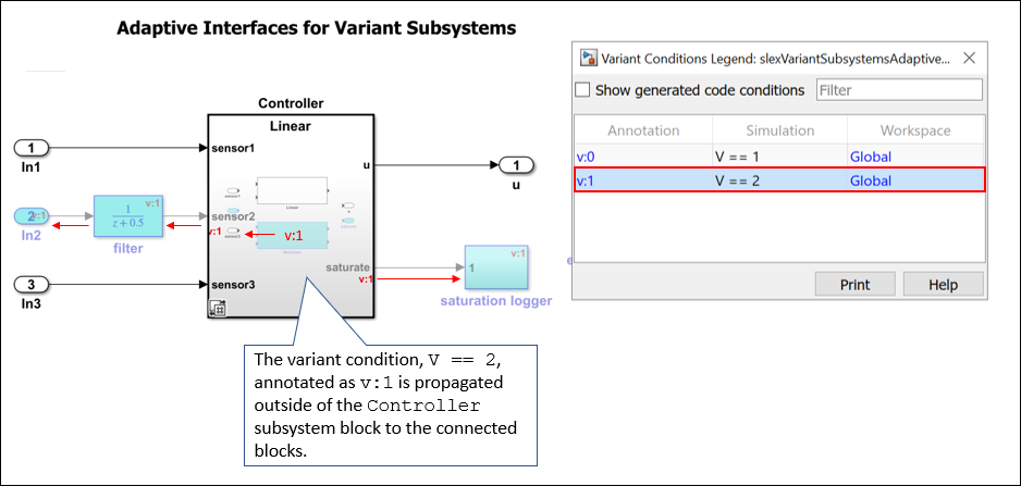
Factors That Affect Propagation of Variant Conditions Outside of Variant Subsystem Blocks
The propagation of variant conditions outside of a Variant Subsystem block depends on the variant activation time of the block and the interface of the underlying variant choices. The Variant activation time parameter determines if Simulink must analyze only the active choice or both active and inactive choices of the block when simulating the model. If the interface of the analyzed variant choices matches the interface of the Variant Subsystem block, the variant conditions do not propagate outside the Variant Subsystem block. In other words, if the analyzed variant choices use all the input and the output signals of the Variant Subsystem block, the variant conditions do not propagate outside of the block. The variant conditions propagate outside of the Variant Subsystem block only if the interfaces do not match.
Adaptive Interface for Variant Subsystems
This example shows how propagating variant conditions outside a Variant Subsystem block enables the block to adapt its interface according to the states of the underlying blocks for different activation times. The example also explains the code that is generated for different activation times. For information on factors that affect the propagation, see Factors That Affect Propagation of Variant Conditions Outside of Variant Subsystem Blocks.
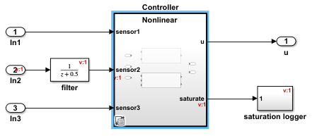
Consider the slexVariantSubsystemsAdaptiveInterface model containing a Variant Subsystem block named Controller with two variant choices, Linear and Nonlinear. The Linear controller is active when V == 1, and the Nonlinear controller is active when V == 2. V is a variant control variable and is defined in the PreLoadFcn callback of the model.
To change the value of the variant control variable, in the MATLAB™ Command Window, type V = 1 or V = 2.
model = "slexVariantSubsystemsAdaptiveInterface";
open_system(model)

Double-click the Controller block to view its contents. The Linear and Nonlinear controller blocks do not have the same interface. The inports sensor1 and sensor3 are used in Linear controller and Nonlinear controller blocks, but sensor2 is used only in Nonlinear controller block. Hence, the sensor2 block is active only when the Nonlinear controller is active and is not executed when the Linear controller is active. To make the model components outside the Controller block aware of the active or inactive state of blocks within the Controller block, the block variant conditions must propagate outside the boundaries of the block. To propagate the variant conditions outside of the Controller block, select Propagate conditions outside of variant subsystem in the Block Parameters dialog box of the block. By default, this parameter is set to off.
To simulate the model and generate code for Linear and Nonlinear controllers, perform these steps:
1. In the Block Parameters dialog box of the Controller block, set an activation time in the Variant activation time parameter.
2. To activate the Linear controller and its connected blocks, change the value of V to 1.
3. Simulate the model and observe the propagated conditions as described in the Propagate Variant Conditions and Generate Code with Different Activation Times section.
4. Generate code from the model by using Embedded Coder® or Simulink Coder®. For information on how to generate the code, see Generate Code Using Embedded Coder (Embedded Coder). Observe the results as described in the Propagate Variant Conditions and Generate Code with Different Activation Times section.
Note
In the model, the saturate port is an unconnected output port and so it is not included in the generated code for any variant activation times.
5. Similarly, to activate the Nonlinear controller and its connected blocks, change the value of V to 2 and simulate the model. Generate code from the model and observe the results.
Propagate Variant Conditions and Generate Code with Different Activation Times
This section explains the simulation results and the code generated for Linear and Nonlinear controllers with different activation times.
Propagate Variant Conditions for update diagram Activation Time
This section compares the propagation of variant conditions for the Linear and Nonlinear controller choices with the update diagram activation time.
When V == 1 and Linear controller is active
Only the
Linearcontroller is analyzed for incompatibilities, such as data type and dimension mismatches.
The
Linearcontroller uses only thesensor1,sensor3anduports, so these ports and their connected blocks are active. TheLinearcontroller does not use thesensor2andsaturateports, so these ports and their connected blocks are inactive. Because the interface of theLinearcontroller is different from the interface of theControllersubsystem, the variant conditions propagate outside of the subsystem. The variant conditions propagate only to the ports that are not used by at least one of the variant choices. In this example, the variant annotationv:2with condition set tofalsepropagates tosensor2,saturate, and all their connected blocks. In the Variant Conditions Legend, a variant condition is set tofalseif the blocks associated with that variant condition are never active.
V = 1;
controllerPath = model+"/Controller";
set_param(controllerPath,"VariantActivationTime","update diagram");
sim(model);
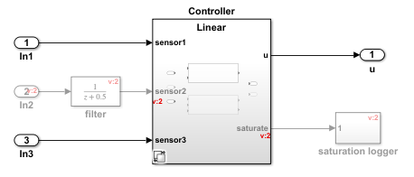
The code that you generate contains only the active ports.
slbuild(model)
### Searching for referenced models in model 'slexVariantSubsystemsAdaptiveInterface'.
### Total of 1 models to build.
### Starting build procedure for: slexVariantSubsystemsAdaptiveInterface
### Successful completion of build procedure for: slexVariantSubsystemsAdaptiveInterface

Build Summary

Top model targets:

Model                                   Build Reason                                         Status                        Build Duration
=========================================================================================================================================
slexVariantSubsystemsAdaptiveInterface  Information cache folder or artifacts were missing.  Code generated and compiled.  0h 0m 15.553s

1 of 1 models built (0 models already up to date)
Build duration: 0h 0m 17.229s
In the C Code tab, select Open Report. Locate and select the slexVariantSubsystemsAdaptiveInterface.h file. Observe that the input port In2 is inactive, so it is not part of the generated code.
cfile=fullfile(pwd, "slexVariantSubsystemsAdaptiveInterface_grt_rtw", "slexVariantSubsystemsAdaptiveInterface.h");
coder.example.extractLines(cfile, "/* External inputs (root inport signals with default storage) */", "/* Real-time Model Data Structure */", 1, 0);
/* External inputs (root inport signals with default storage) */
typedef struct {
  real_T In1;                          /* '<Root>/In1' */
  real_T In3;                          /* '<Root>/In3' */
} ExtU_slexVariantSubsystemsAda_T;

/* External outputs (root outports fed by signals with default storage) */
typedef struct {
  real_T u;                            /* '<Root>/u' */
} ExtY_slexVariantSubsystemsAda_T;
The active choice is unconditional. Unconditional statements are not enclosed in any conditional statements and are compiled or executed irrespective of the state of the variant choices.
cfile=fullfile(pwd, "slexVariantSubsystemsAdaptiveInterface_grt_rtw", "slexVariantSubsystemsAdaptiveInterface.c");
coder.example.extractLines(cfile, "/* Model step", "/* Model initialize", 1, 0);
/* Model step function */
void slexVariantSubsystemsAdaptiveInterface_step(void)
{
  real_T denAccum;

  /* Outputs for Atomic SubSystem: '<S1>/Linear' */
  /* Outport: '<Root>/u' incorporates:
   *  DiscreteTransferFcn: '<S2>/Discrete Transfer Fcn'
   */
  slexVariantSubsystemsAdaptive_Y.u = 0.24 *
    slexVariantSubsystemsAdaptiv_DW.DiscreteTransferFcn_states[0] + 0.21 *
    slexVariantSubsystemsAdaptiv_DW.DiscreteTransferFcn_states[1];

  /* Update for DiscreteTransferFcn: '<S2>/Discrete Transfer Fcn' incorporates:
   *  Gain: '<S2>/Gain'
   *  Inport: '<Root>/In1'
   *  Inport: '<Root>/In3'
   *  Sum: '<S2>/Sum'
   */
  denAccum = ((slexVariantSubsystemsAdaptive_U.In1 +
               slexVariantSubsystemsAdaptive_U.In3) * 0.5 - 1.1 *
              slexVariantSubsystemsAdaptiv_DW.DiscreteTransferFcn_states[0]) -
    0.48 * slexVariantSubsystemsAdaptiv_DW.DiscreteTransferFcn_states[1];
  slexVariantSubsystemsAdaptiv_DW.DiscreteTransferFcn_states[1] =
    slexVariantSubsystemsAdaptiv_DW.DiscreteTransferFcn_states[0];
  slexVariantSubsystemsAdaptiv_DW.DiscreteTransferFcn_states[0] = denAccum;

  /* End of Outputs for SubSystem: '<S1>/Linear' */

  /* Matfile logging */
  rt_UpdateTXYLogVars(slexVariantSubsystemsAdaptiv_M->rtwLogInfo,
                      (&slexVariantSubsystemsAdaptiv_M->Timing.taskTime0));

  /* signal main to stop simulation */
  {                                    /* Sample time: [1.0s, 0.0s] */
    if ((rtmGetTFinal(slexVariantSubsystemsAdaptiv_M)!=-1) &&
        !((rtmGetTFinal(slexVariantSubsystemsAdaptiv_M)-
           slexVariantSubsystemsAdaptiv_M->Timing.taskTime0) >
          slexVariantSubsystemsAdaptiv_M->Timing.taskTime0 * (DBL_EPSILON))) {
      rtmSetErrorStatus(slexVariantSubsystemsAdaptiv_M, "Simulation finished");
    }
  }

  /* Update absolute time for base rate */
  /* The "clockTick0" counts the number of times the code of this task has
   * been executed. The absolute time is the multiplication of "clockTick0"
   * and "Timing.stepSize0". Size of "clockTick0" ensures timer will not
   * overflow during the application lifespan selected.
   * Timer of this task consists of two 32 bit unsigned integers.
   * The two integers represent the low bits Timing.clockTick0 and the high bits
   * Timing.clockTickH0. When the low bit overflows to 0, the high bits increment.
   */
  if (!(++slexVariantSubsystemsAdaptiv_M->Timing.clockTick0)) {
    ++slexVariantSubsystemsAdaptiv_M->Timing.clockTickH0;
  }

  slexVariantSubsystemsAdaptiv_M->Timing.taskTime0 =
    slexVariantSubsystemsAdaptiv_M->Timing.clockTick0 *
    slexVariantSubsystemsAdaptiv_M->Timing.stepSize0 +
    slexVariantSubsystemsAdaptiv_M->Timing.clockTickH0 *
    slexVariantSubsystemsAdaptiv_M->Timing.stepSize0 * 4294967296.0;
}
When V == 2 and Nonlinear controller is active
Only the
Nonlinearcontroller is analyzed for incompatibilities, such as data type and dimension mismatches.
The
Nonlinearcontroller uses all the input and output ports of theControllerblock, so all the input ports,sensor1,sensor2, andsensor3, and all their connected blocks are active. Also, both output ports,uandsaturate, and all their connected blocks are active. Because the interface of theNonlinearcontroller matches the interface of theControllersubsystem, the variant conditions do not propagate outside of theControllersubsystem block.
V = 2;
set_param(controllerPath,"VariantActivationTime","update diagram");
sim(model);
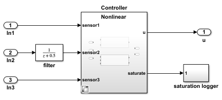
The code that you generate contains only the active ports.
slbuild(model)
### Searching for referenced models in model 'slexVariantSubsystemsAdaptiveInterface'.
### Total of 1 models to build.
### Starting build procedure for: slexVariantSubsystemsAdaptiveInterface
### Successful completion of build procedure for: slexVariantSubsystemsAdaptiveInterface

Build Summary

Top model targets:

Model                                   Build Reason                Status                        Build Duration
================================================================================================================
slexVariantSubsystemsAdaptiveInterface  Global variable V changed.  Code generated and compiled.  0h 0m 6.5456s

1 of 1 models built (0 models already up to date)
Build duration: 0h 0m 6.9824s
In the C Code tab, select Open Report. Locate and select the slexVariantSubsystemsAdaptiveInterface.h file. Observe that all the input and the output ports are active and so they are part of the generated code.
cfile=fullfile(pwd, "slexVariantSubsystemsAdaptiveInterface_grt_rtw", "slexVariantSubsystemsAdaptiveInterface.h");
coder.example.extractLines(cfile, "/* External inputs (root inport signals with default storage) */", "/* Real-time Model Data Structure */", 1, 0);
/* External inputs (root inport signals with default storage) */
typedef struct {
  real_T In1;                          /* '<Root>/In1' */
  real_T In2;                          /* '<Root>/In2' */
  real_T In3;                          /* '<Root>/In3' */
} ExtU_slexVariantSubsystemsAda_T;

/* External outputs (root outports fed by signals with default storage) */
typedef struct {
  real_T u;                            /* '<Root>/u' */
} ExtY_slexVariantSubsystemsAda_T;
The active choice is unconditional. The unconditional statements are not enclosed in any conditional statements and are compiled or executed irrespective of the state of the variant choices.
cfile=fullfile(pwd, "slexVariantSubsystemsAdaptiveInterface_grt_rtw", "slexVariantSubsystemsAdaptiveInterface.c");
coder.example.extractLines(cfile, "/* Model step", "/* Model initialize", 1, 0);
/* Model step function */
void slexVariantSubsystemsAdaptiveInterface_step(void)
{
  real_T denAccum;

  /* Outputs for Atomic SubSystem: '<S1>/Nonlinear' */
  /* Lookup_n-D: '<S3>/Lookup Table' incorporates:
   *  DiscreteTransferFcn: '<S3>/Discrete Transfer Fcn'
   */
  slexVariantSubsystemsAdaptive_B.LookupTable = 0.24 *
    slexVariantSubsystemsAdaptiv_DW.DiscreteTransferFcn_states[0] + 0.21 *
    slexVariantSubsystemsAdaptiv_DW.DiscreteTransferFcn_states[1];

  /* Saturate: '<S3>/Saturation' */
  if (slexVariantSubsystemsAdaptive_B.LookupTable > 0.5) {
    /* Outport: '<Root>/u' */
    slexVariantSubsystemsAdaptive_Y.u = 0.5;
  } else if (slexVariantSubsystemsAdaptive_B.LookupTable < -0.5) {
    /* Outport: '<Root>/u' */
    slexVariantSubsystemsAdaptive_Y.u = -0.5;
  } else {
    /* Outport: '<Root>/u' */
    slexVariantSubsystemsAdaptive_Y.u =
      slexVariantSubsystemsAdaptive_B.LookupTable;
  }

  /* End of Saturate: '<S3>/Saturation' */

  /* Lookup_n-D: '<S3>/Lookup Table' incorporates:
   *  DiscreteTransferFcn: '<Root>/filter'
   *  Gain: '<S3>/Gain'
   *  Inport: '<Root>/In1'
   *  Inport: '<Root>/In3'
   *  Sum: '<S3>/Sum'
   */
  slexVariantSubsystemsAdaptive_B.LookupTable =
    ((slexVariantSubsystemsAdaptive_U.In1 +
      slexVariantSubsystemsAdaptiv_DW.filter_states) +
     slexVariantSubsystemsAdaptive_U.In3) * 0.33333333333333331;
  slexVariantSubsystemsAdaptive_B.LookupTable = look1_binlxpw
    (slexVariantSubsystemsAdaptive_B.LookupTable,
     slexVariantSubsystemsAda_ConstP.LookupTable_bp01Data,
     slexVariantSubsystemsAda_ConstP.LookupTable_tableData, 4U);

  /* Update for DiscreteTransferFcn: '<S3>/Discrete Transfer Fcn' */
  denAccum = (slexVariantSubsystemsAdaptive_B.LookupTable - 1.1 *
              slexVariantSubsystemsAdaptiv_DW.DiscreteTransferFcn_states[0]) -
    0.48 * slexVariantSubsystemsAdaptiv_DW.DiscreteTransferFcn_states[1];
  slexVariantSubsystemsAdaptiv_DW.DiscreteTransferFcn_states[1] =
    slexVariantSubsystemsAdaptiv_DW.DiscreteTransferFcn_states[0];
  slexVariantSubsystemsAdaptiv_DW.DiscreteTransferFcn_states[0] = denAccum;

  /* End of Outputs for SubSystem: '<S1>/Nonlinear' */

  /* Update for DiscreteTransferFcn: '<Root>/filter' incorporates:
   *  Inport: '<Root>/In2'
   */
  slexVariantSubsystemsAdaptiv_DW.filter_states =
    slexVariantSubsystemsAdaptive_U.In2 - 0.5 *
    slexVariantSubsystemsAdaptiv_DW.filter_states;

  /* Matfile logging */
  rt_UpdateTXYLogVars(slexVariantSubsystemsAdaptiv_M->rtwLogInfo,
                      (&slexVariantSubsystemsAdaptiv_M->Timing.taskTime0));

  /* signal main to stop simulation */
  {                                    /* Sample time: [1.0s, 0.0s] */
    if ((rtmGetTFinal(slexVariantSubsystemsAdaptiv_M)!=-1) &&
        !((rtmGetTFinal(slexVariantSubsystemsAdaptiv_M)-
           slexVariantSubsystemsAdaptiv_M->Timing.taskTime0) >
          slexVariantSubsystemsAdaptiv_M->Timing.taskTime0 * (DBL_EPSILON))) {
      rtmSetErrorStatus(slexVariantSubsystemsAdaptiv_M, "Simulation finished");
    }
  }

  /* Update absolute time for base rate */
  /* The "clockTick0" counts the number of times the code of this task has
   * been executed. The absolute time is the multiplication of "clockTick0"
   * and "Timing.stepSize0". Size of "clockTick0" ensures timer will not
   * overflow during the application lifespan selected.
   * Timer of this task consists of two 32 bit unsigned integers.
   * The two integers represent the low bits Timing.clockTick0 and the high bits
   * Timing.clockTickH0. When the low bit overflows to 0, the high bits increment.
   */
  if (!(++slexVariantSubsystemsAdaptiv_M->Timing.clockTick0)) {
    ++slexVariantSubsystemsAdaptiv_M->Timing.clockTickH0;
  }

  slexVariantSubsystemsAdaptiv_M->Timing.taskTime0 =
    slexVariantSubsystemsAdaptiv_M->Timing.clockTick0 *
    slexVariantSubsystemsAdaptiv_M->Timing.stepSize0 +
    slexVariantSubsystemsAdaptiv_M->Timing.clockTickH0 *
    slexVariantSubsystemsAdaptiv_M->Timing.stepSize0 * 4294967296.0;
}
Note: When propagating the variant conditions outside of a Variant Subsystem block with the update diagram activation time:
The variant conditions that propagate is the same regardless of the setting of Built-in passthrough choice. The code that you generate with Built-in passthrough choice selected, bypasses the variant region by assigning the input values of the Variant Subsystem block to its output ports when none of the variant choices are active.
If you select Built-in empty choice, Simulink propagates the variant conditions to all the blocks (including the unconditional or always true blocks) of the variant region. Propagating conditions to all the blocks of the variant region enables Simulink to completely remove the variant region from the model when none of the variant choices are active. The code that you generate is the same regardless of the setting of Built-in empty choice.
Propagate Variant Conditions for update diagram analyze all choices Activation Time
This section compares the propagation of variant conditions for the Linear and Nonlinear controller choices with the update diagram analyze all choices activation time. The generated code is the same as with the update diagram activation time.
When V == 1 and Linear controller is active
The
Linearcontroller andNonlinearcontroller choices are analyzed for incompatibilities, such as data type and dimension mismatches.
The
Linearcontroller uses only thesensor1,sensor3, anduports, so these ports and their connected blocks are active. TheLinearcontroller does not usesensor2andsaturateports, so these ports and their connected blocks are inactive.
Since the interface of the
Linearcontroller does not match the interface of theControllersubsystem, the variant conditions propagate outside of theControllersubsystem block. The variant conditions propagate only to the ports that are not used by at least one of the variant choices. In this example, the variant with annotationv:1and with variant condition set toV == 2propagates to thesensor2,saturate, and their connected blocks.
V = 1;
set_param(controllerPath,"VariantActivationTime","update diagram analyze all choices");
sim(model);
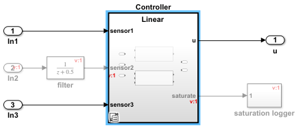
When V == 2 and Nonlinear controller is active
The
Linearcontroller andNonlinearcontroller choices are analyzed for incompatibilities, such as data type and dimension mismatches.
The
Nonlinearcontroller uses all the input and output ports of theControllersubsystem, so all the input ports,sensor1,sensor2, andsensor3, and all their connected blocks are active. Also, both output ports,uandsaturate, and all their connected blocks are active.
Since the interface of the
Linearcontroller does not match the interface of theControllersubsystem, the variant conditions propagate outside of theControllersubsystem block. The variant conditions propagate only to the ports that are not used by at least one of the variant choices. In this example, the variant with annotationv:1and with variant condition set toV == 2propagates tosensor2,saturate, and their connected blocks.
V = 2;
set_param(controllerPath,"VariantActivationTime","update diagram analyze all choices");
sim(model);
Note: When propagating variant conditions outside of a Variant Subsystem block with the update diagram analyze all choices activation time:
The variant conditions that propagate is the same regardless of the setting of Built-in passthrough choice. The code that you generate with Built-in passthrough choice selected, bypasses the variant region by assigning the input values of the Variant Subsystem block to its output ports when none of the variant choices are active.
If you set Built-in empty choice to
on, Simulink propagates the variant conditions to the all the blocks (including the always true or unconditional blocks) of the variant region. Propagating conditions to all the blocks of the variant region enables Simulink to completely remove the variant region from the model when none of the variant choices are active. The code that you generate is the same regardless of the setting of Built-in empty choice.
Propagate Variant Conditions for code compile Activation Time
The propagation of variant conditions for the Linear and Nonlinear controller choices with the code compile activation time is the same as propagation with the update diagram analyze all choices activation time.
If you have an Embedded Coder® license and the model specifies an ERT-based system target file, for example, ert.tlc, the slexVariantSubsystemsAdaptiveInterface.c file contains the Linear and Nonlinear choices guarded by preprocessor conditionals #if and #elif. The preprocessor conditionals enable you to conditionally compile the code based on specific choices. For more information, see Compile Code Conditionally for Variations of Component Represented Using Variant Block (Simulink Coder).
The code that is generated for the Linear and Nonlinear controllers is as shown.
set_param(model,"SystemTargetFile","ert.tlc");
set_param(controllerPath,"VariantActivationTime","code compile");
slbuild(model);
### Searching for referenced models in model 'slexVariantSubsystemsAdaptiveInterface'.
### Total of 1 models to build.
### Starting build procedure for: slexVariantSubsystemsAdaptiveInterface
### Successful completion of build procedure for: slexVariantSubsystemsAdaptiveInterface

Build Summary

Top model targets:

Model                                   Build Reason                                         Status                        Build Duration
=========================================================================================================================================
slexVariantSubsystemsAdaptiveInterface  Information cache folder or artifacts were missing.  Code generated and compiled.  0h 0m 9.1075s

1 of 1 models built (0 models already up to date)
Build duration: 0h 0m 9.5478s
cfile=fullfile(pwd, "slexVariantSubsystemsAdaptiveInterface_ert_rtw", "slexVariantSubsystemsAdaptiveInterface.c");
coder.example.extractLines(cfile, "/* Model step", "/* Model initialize", 1, 0);
/* Model step function */
void slexVariantSubsystemsAdaptiveInterface_step(void)
{

#if (V == 1) || (V == 2)

  real_T denAccum;

#endif

  /* DiscreteTransferFcn: '<Root>/filter' incorporates:
   *  Inport: '<Root>/In2'
   */
#if V == 2

  /* Outputs for Atomic SubSystem: '<Root>/Controller' */
  /* Outputs for Atomic SubSystem: '<S1>/Nonlinear' */
  /* VariantMerge generated from: '<S1>/u' incorporates:
   *  DiscreteTransferFcn: '<S4>/Discrete Transfer Fcn'
   */
  slexVariantSubsystemsAdaptive_Y.u = 0.24 *
    slexVariantSubsystemsAdaptiv_DW.DiscreteTransferFcn_states[0] + 0.21 *
    slexVariantSubsystemsAdaptiv_DW.DiscreteTransferFcn_states[1];

  /* Saturate: '<S4>/Saturation' incorporates:
   *  DiscreteTransferFcn: '<S4>/Discrete Transfer Fcn'
   */
  if (slexVariantSubsystemsAdaptive_Y.u > 0.5) {
    /* VariantMerge generated from: '<S1>/u' */
    slexVariantSubsystemsAdaptive_Y.u = 0.5;
  } else if (slexVariantSubsystemsAdaptive_Y.u < -0.5) {
    /* VariantMerge generated from: '<S1>/u' */
    slexVariantSubsystemsAdaptive_Y.u = -0.5;
  }

  /* End of Saturate: '<S4>/Saturation' */

  /* Update for DiscreteTransferFcn: '<S4>/Discrete Transfer Fcn' incorporates:
   *  Gain: '<S4>/Gain'
   *  Inport: '<Root>/In1'
   *  Inport: '<Root>/In3'
   *  Lookup_n-D: '<S4>/Lookup Table'
   *  Sum: '<S4>/Sum'
   */
  denAccum = (look1_binlxpw(((slexVariantSubsystemsAdaptive_U.In1 +
    slexVariantSubsystemsAdaptiv_DW.filter_states) +
    slexVariantSubsystemsAdaptive_U.In3) * 0.33333333333333331,
    slexVariantSubsystemsAda_ConstP.LookupTable_bp01Data,
    slexVariantSubsystemsAda_ConstP.LookupTable_tableData, 4U) - 1.1 *
              slexVariantSubsystemsAdaptiv_DW.DiscreteTransferFcn_states[0]) -
    0.48 * slexVariantSubsystemsAdaptiv_DW.DiscreteTransferFcn_states[1];
  slexVariantSubsystemsAdaptiv_DW.DiscreteTransferFcn_states[1] =
    slexVariantSubsystemsAdaptiv_DW.DiscreteTransferFcn_states[0];
  slexVariantSubsystemsAdaptiv_DW.DiscreteTransferFcn_states[0] = denAccum;
  slexVariantSubsystemsAdaptiv_DW.filter_states =
    slexVariantSubsystemsAdaptive_U.In2 - 0.5 *
    slexVariantSubsystemsAdaptiv_DW.filter_states;

  /* End of Outputs for SubSystem: '<S1>/Nonlinear' */
  /* End of Outputs for SubSystem: '<Root>/Controller' */
#elif V == 1

  /* Outputs for Atomic SubSystem: '<S1>/Linear' */
  /* Update for DiscreteTransferFcn: '<S3>/Discrete Transfer Fcn' incorporates:
   *  Gain: '<S3>/Gain'
   *  Inport: '<Root>/In1'
   *  Inport: '<Root>/In3'
   *  Sum: '<S3>/Sum'
   */
  denAccum = ((slexVariantSubsystemsAdaptive_U.In1 +
               slexVariantSubsystemsAdaptive_U.In3) * 0.5 - 1.1 *
              slexVariantSubsystemsAdaptiv_DW.DiscreteTransferFcn_states_k[0]) -
    0.48 * slexVariantSubsystemsAdaptiv_DW.DiscreteTransferFcn_states_k[1];

  /* VariantMerge generated from: '<S1>/u' incorporates:
   *  DiscreteTransferFcn: '<S3>/Discrete Transfer Fcn'
   */
  slexVariantSubsystemsAdaptive_Y.u = 0.24 *
    slexVariantSubsystemsAdaptiv_DW.DiscreteTransferFcn_states_k[0] + 0.21 *
    slexVariantSubsystemsAdaptiv_DW.DiscreteTransferFcn_states_k[1];

  /* Update for DiscreteTransferFcn: '<S3>/Discrete Transfer Fcn' */
  slexVariantSubsystemsAdaptiv_DW.DiscreteTransferFcn_states_k[1] =
    slexVariantSubsystemsAdaptiv_DW.DiscreteTransferFcn_states_k[0];
  slexVariantSubsystemsAdaptiv_DW.DiscreteTransferFcn_states_k[0] = denAccum;

  /* End of Outputs for SubSystem: '<S1>/Linear' */
#endif

  /* End of DiscreteTransferFcn: '<Root>/filter' */
}
The port sensor2, which is not used by all the variant choices, is also enclosed in preprocessor conditional #if.
cfile=fullfile(pwd, "slexVariantSubsystemsAdaptiveInterface_ert_rtw", "slexVariantSubsystemsAdaptiveInterface.h");
coder.example.extractLines(cfile, "/* External inputs (root inport signals with default storage) */", "/* Real-time Model Data Structure */", 1, 0);
/* External inputs (root inport signals with default storage) */
typedef struct {
  real_T In1;                          /* '<Root>/In1' */

#if V == 2

  real_T In2;                          /* '<Root>/In2' */

#endif

  real_T In3;                          /* '<Root>/In3' */
} ExtU_slexVariantSubsystemsAda_T;

/* External outputs (root outports fed by signals with default storage) */
typedef struct {
  real_T u;                            /* '<Root>/u' */
} ExtY_slexVariantSubsystemsAda_T;
Note: When propagating variant conditions outside of a Variant Subsystem block with the code compile activation time:
The variant conditions that propagate is the same regardless of the setting of Built-in passthrough choice. The code that you generate with Built-in passthrough choice selected, bypasses the variant region by assigning the input values of the Variant Subsystem block to its output ports when none of the variant choices are active.
If you select Built-in empty choice, Simulink propagates the variant conditions to all the blocks (including the always
trueor unconditional blocks) of the variant region. In the generated code, the blocks of the variant region are guarded by an additional variant condition that is the logicalORof variant conditions from the variant choices. This enables Simulink to remove the variant regions completely from the model when none of the variant choices are active. In this example, the alwaystrueblocksIn1andIn3, and the variant choicesLinearandNonlinearare guarded by the logicalORof variant conditions,V == 1||V == 2. WhenV == 1andV == 2each evaluate tofalse, Simulink skips the compilation of these blocks thus removing the variant regions completely.
Propagate Variant Conditions for startup Activation Time
The propagation of variant conditions for the Linear and Nonlinear controller choices with the startup activation time is the same as propagation with the update diagram analyze all choices activation time.
The code that is generated for the Linear and Nonlinear controllers is as shown. In the slexVariantSubsystemsAdaptiveInterface.c file, the Linear and Nonlinear choices are guarded by if and else if conditional statements. The conditions enable you to conditionally execute startup routines based on specific choices. For more information, see Run Executables for Variant Blocks Without Recompiling Code for Changing Active Choices Using Startup Activation Time (Simulink Coder).
set_param(controllerPath,"VariantActivationTime","startup");
slbuild(model)
### Searching for referenced models in model 'slexVariantSubsystemsAdaptiveInterface'.
### Total of 1 models to build.
### Starting build procedure for: slexVariantSubsystemsAdaptiveInterface
### Successful completion of build procedure for: slexVariantSubsystemsAdaptiveInterface

Build Summary

Top model targets:

Model                                   Build Reason                     Status                        Build Duration
=====================================================================================================================
slexVariantSubsystemsAdaptiveInterface  Generated code was out of date.  Code generated and compiled.  0h 0m 5.371s

1 of 1 models built (0 models already up to date)
Build duration: 0h 0m 5.8965s
cfile=fullfile(pwd, "slexVariantSubsystemsAdaptiveInterface_ert_rtw", "slexVariantSubsystemsAdaptiveInterface.c");
coder.example.extractLines(cfile, "/* Model step", "/* Model terminate", 1, 0);
/* Model step function */
void slexVariantSubsystemsAdaptiveInterface_step(void)
{
  real_T denAccum;

  /* Outputs for Atomic SubSystem: '<Root>/Controller' */
  /* DiscreteTransferFcn: '<Root>/filter' */
  if (slex_V_VariantControlExpression == 2.0) {
    /* Outputs for Atomic SubSystem: '<S1>/Nonlinear' */
    /* VariantMerge generated from: '<S1>/u' incorporates:
     *  DiscreteTransferFcn: '<S4>/Discrete Transfer Fcn'
     */
    slexVariantSubsystemsAdaptive_Y.u = 0.24 *
      slexVariantSubsystemsAdaptiv_DW.DiscreteTransferFcn_states[0] + 0.21 *
      slexVariantSubsystemsAdaptiv_DW.DiscreteTransferFcn_states[1];

    /* Saturate: '<S4>/Saturation' incorporates:
     *  DiscreteTransferFcn: '<S4>/Discrete Transfer Fcn'
     */
    if (slexVariantSubsystemsAdaptive_Y.u > 0.5) {
      /* VariantMerge generated from: '<S1>/u' */
      slexVariantSubsystemsAdaptive_Y.u = 0.5;
    } else if (slexVariantSubsystemsAdaptive_Y.u < -0.5) {
      /* VariantMerge generated from: '<S1>/u' */
      slexVariantSubsystemsAdaptive_Y.u = -0.5;
    }

    /* End of Saturate: '<S4>/Saturation' */

    /* Update for DiscreteTransferFcn: '<S4>/Discrete Transfer Fcn' incorporates:
     *  Gain: '<S4>/Gain'
     *  Inport: '<Root>/In1'
     *  Inport: '<Root>/In3'
     *  Lookup_n-D: '<S4>/Lookup Table'
     *  Sum: '<S4>/Sum'
     */
    denAccum = (look1_binlxpw(((slexVariantSubsystemsAdaptive_U.In1 +
      slexVariantSubsystemsAdaptiv_DW.filter_states) +
      slexVariantSubsystemsAdaptive_U.In3) * 0.33333333333333331,
      slexVariantSubsystemsAda_ConstP.LookupTable_bp01Data,
      slexVariantSubsystemsAda_ConstP.LookupTable_tableData, 4U) - 1.1 *
                slexVariantSubsystemsAdaptiv_DW.DiscreteTransferFcn_states[0]) -
      0.48 * slexVariantSubsystemsAdaptiv_DW.DiscreteTransferFcn_states[1];
    slexVariantSubsystemsAdaptiv_DW.DiscreteTransferFcn_states[1] =
      slexVariantSubsystemsAdaptiv_DW.DiscreteTransferFcn_states[0];
    slexVariantSubsystemsAdaptiv_DW.DiscreteTransferFcn_states[0] = denAccum;

    /* End of Outputs for SubSystem: '<S1>/Nonlinear' */
  } else if (slex_V_VariantControlExpression == 1.0) {
    /* Outputs for Atomic SubSystem: '<S1>/Linear' */
    /* Update for DiscreteTransferFcn: '<S3>/Discrete Transfer Fcn' incorporates:
     *  Gain: '<S3>/Gain'
     *  Inport: '<Root>/In1'
     *  Inport: '<Root>/In3'
     *  Sum: '<S3>/Sum'
     */
    denAccum = ((slexVariantSubsystemsAdaptive_U.In1 +
                 slexVariantSubsystemsAdaptive_U.In3) * 0.5 - 1.1 *
                slexVariantSubsystemsAdaptiv_DW.DiscreteTransferFcn_states_k[0])
      - 0.48 * slexVariantSubsystemsAdaptiv_DW.DiscreteTransferFcn_states_k[1];

    /* VariantMerge generated from: '<S1>/u' incorporates:
     *  DiscreteTransferFcn: '<S3>/Discrete Transfer Fcn'
     */
    slexVariantSubsystemsAdaptive_Y.u = 0.24 *
      slexVariantSubsystemsAdaptiv_DW.DiscreteTransferFcn_states_k[0] + 0.21 *
      slexVariantSubsystemsAdaptiv_DW.DiscreteTransferFcn_states_k[1];

    /* Update for DiscreteTransferFcn: '<S3>/Discrete Transfer Fcn' */
    slexVariantSubsystemsAdaptiv_DW.DiscreteTransferFcn_states_k[1] =
      slexVariantSubsystemsAdaptiv_DW.DiscreteTransferFcn_states_k[0];
    slexVariantSubsystemsAdaptiv_DW.DiscreteTransferFcn_states_k[0] = denAccum;

    /* End of Outputs for SubSystem: '<S1>/Linear' */
  }

  /* End of DiscreteTransferFcn: '<Root>/filter' */
  /* End of Outputs for SubSystem: '<Root>/Controller' */

  /* Update for DiscreteTransferFcn: '<Root>/filter' incorporates:
   *  Inport: '<Root>/In2'
   */
  if (slex_V_VariantControlExpression == 2.0) {
    slexVariantSubsystemsAdaptiv_DW.filter_states =
      slexVariantSubsystemsAdaptive_U.In2 - 0.5 *
      slexVariantSubsystemsAdaptiv_DW.filter_states;
  }

  /* End of Update for DiscreteTransferFcn: '<Root>/filter' */
}

/* Model initialize function */
void slexVariantSubsystemsAdaptiveInterface_initialize(void)
{
  slexVaria_startupVariantChecker();
}
In the slexVariantSubsystemsAdaptiveInterface.h file, the ports are unconditional to avoid issues with incomplete or inconsistent initial configurations.
cfile=fullfile(pwd, "slexVariantSubsystemsAdaptiveInterface_ert_rtw", "slexVariantSubsystemsAdaptiveInterface.h");
coder.example.extractLines(cfile, "/* External inputs (root inport signals with default storage) */", "/* Real-time Model Data Structure */", 1, 0);
/* External inputs (root inport signals with default storage) */
typedef struct {
  real_T In1;                          /* '<Root>/In1' */
  real_T In2;                          /* '<Root>/In2' */
  real_T In3;                          /* '<Root>/In3' */
} ExtU_slexVariantSubsystemsAda_T;

/* External outputs (root outports fed by signals with default storage) */
typedef struct {
  real_T u;                            /* '<Root>/u' */
} ExtY_slexVariantSubsystemsAda_T;
Note: When propagating variant conditions outside of a Variant Subsystem block with the startup activation time:
The variant conditions that propagate is the same regardless of the setting of Built-in passthrough choice. The code that you generate with Built-in passthrough choice selected, bypasses the variant region by assigning the input values of the Variant Subsystem block to its output ports when none of the variant choices are active.
If you select Built-in empty choice, Simulink propagates the variant conditions to all the blocks (including the always true or unconditional blocks) of the variant region. In the generated code, the blocks of the variant region are guarded by an additional variant condition that is the logical
ORof variant conditions from the variant choices. This enables Simulink to remove the variant regions completely from the model when none of the variant choices are active. In this example, the always true blocksIn1andIn3, and the variant choicesLinearandNonlinearare guarded by the logicalORof the variant conditions,V == 1||V == 2. WhenV == 1andV == 2each evaluate tofalse, Simulink skips the compilation of these blocks thus removing the variant regions completely.
Limitations
The variant conditions propagated from the Variant Subsystem blocks can be set on Simscape™ and Stateflow® blocks only for the update diagram variant activation time.
Propagation Without Inport and Outport Blocks
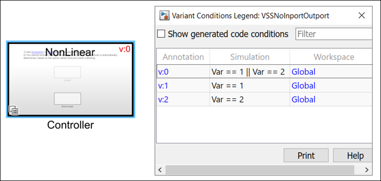
Consider this model that has a Variant Subsystem block Controller
with two variant choices. The block does not have any inports or outports. The first variant
choice has the condition V == 1, while the second variant choice has the
condition W == 1.
In this model, the variant conditions from the Controller block
without inports or outports propagate outside the subsystem in the same way as a
Variant Subsystem block with inports and outports. The activation times and
the allowance of zero active variant controls also have the same impact on condition
propagation.
During simulation with these settings, the variant conditions propagate as follows:
When you set the Propagate conditions outside of variant subsystem parameter to
off, no variant conditions apply to theControllerblock. This is because the interface of theControllerblock remain the same regardless of the active choice due to its shared interface with the choice blocks. When you set the Propagate conditions outside of variant subsystem parameter toon, the variant condition of the active choice applies to theControllerblock so that the variant condition propagates to the connected blocks, if any. In this example, no blocks that connected.With the Built-in empty choice parameter set to
on, the variant conditions propagate to all blocks within the variant region, including unconditional blocks such as theControllerblock in this example, enabling the complete elimination of the variant region when none of the choices are active.Setting the Variant activation time parameter to
code compileorstartup, adds an additional variant condition in the generated code that encloses the blocks within the variant region. In this example, the variant condition is a logical OR of the variant conditionsV == 1andW == 1.
Limitations
Propagated variant conditions from variant subsystems can be set on Simscape™ or Stateflow® blocks only for the update diagram variant
activation time.
See Also
Implement Variations in Separate Hierarchy Using Variant Subsystems | Propagate Variant Conditions to Define Variant Regions with Variant Blocks