Select Subsystem Execution
A logically executed subsystem block runs one or more times at the current time step when enabled by a control block. A control block implements control logic similar to that expressed by a programming language statement (e.g., if-then, switch, while, for).
Selector subsystems are one type of logically executed subsystem that execute once during a time step in response to an action signal from a control block located external to the subsystem. Simulink® supports two selector subsystem structures, if-else and switch-case.
Models with If-Else Structures
The If Action Subsystem block is a Subsystem block preconfigured as a starting point for creating a subsystem whose execution is enabled by an If block.
An external If block controls execution. The If block evaluates a logical expression and then, depending on the result of the evaluation, outputs an action signal to an If Action Subsystem block.
Merge Signals from If Action Subsystem Blocks
The example model ex_if_block shows how to merge signals controlled by an If block.
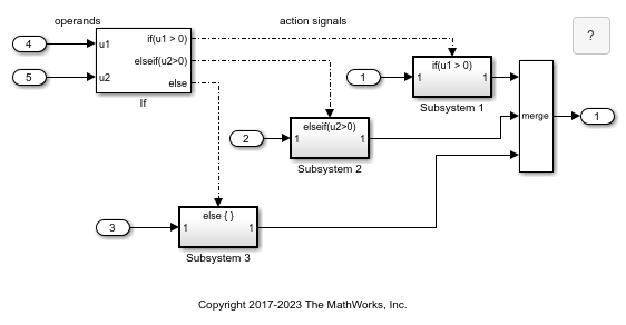
The If block selects the execution of an If Action Subsystem block from a set of subsystems. Regardless of which subsystem the If block selects, you can create one output signal with a Merge block.
All blocks in an If Action Subsystem block must execute at the same rate as the driving If block. To satisfy this requirement, set the sample time parameter for each block to either inherited (-1) or the same value as the If block sample time.
The inputs to the If block provide the operand values for the logical expressions represented as output ports. Each output port is attached to an If Action Subsystem block. The expressions in the If block are evaluated top down starting with the if expression. When an expression evaluates to true, its corresponding If Action Subsystem is executed, and the remaining expressions are not evaluated.
The if-else structure in the model can be represented with this pseudo code.
IF u1 > 0 THEN
    Subsystem 1
ELSEIF u2 > 0
    Subsystem 2
ELSE
    Subsystem 3
END IF
Create Model with If-Else Structure
To create the example model, use this procedure.
Place an If block in the Simulink Editor. Double-click the block to open the block parameters dialog box.
In the Number of inputs box, enter
2.Two input ports are added to the block. The inputs ports are for signals containing operand values, not necessary the number of operands. An input signal can be a vector. For example, you could specify the fifth element of a vector u in an expression as
u(5) > 0.In the If expression text box, enter
u1 > 0.An output port is added to the block with the label
if(u1 > 0). This port is the only required output for an If block.In the Elseif expressions text box, enter
u2 > 0.You can enter multiple elseif expressions with a comma separating the expressions. Each expression adds an output port to the If block with a label of the form
elseif(expression).Check the Show else condition check box.
An output port is added to the block with the label
else.Add three If Action Subsystem blocks.
These blocks are Subsystem blocks with an Action Port block. When you place an Action Port block inside a subsystem, an input port named Action is added to the block.
Connect each output port from the If block to the action port of an If Action Subsystem block.
When you make the connection, the icon for the If Action Subsystem block is renamed to the type of expression that attached to it.
In each If Action Subsystem block, enter the Simulink blocks to be executed for the condition it handles.
Connect outputs from If Action Subsystem blocks to a Merge block.
Run a simulation.
The action signal lines between the If block and the If Action Subsystem blocks change from a solid to a dashed line.
Note
All blocks in an If Action Subsystem block driven by an If block must run at the same rate as the driving block.
Models with Switch Case Structure
The Switch Case Action Subsystem block is a Subsystem block preconfigured as a starting point for creating a subsystem whose execution is enabled by a Switch Case block.
An external Switch Case block controls execution. The Switch Case block evaluates a case index and then, depending on the selected case, outputs an action signal to a Switch Case Action Subsystem block.
Merge Signals from Switch Case Action Subsystem Blocks
The example model ex_switch_case_block shows how to create one signal from multiple subsystem output signals.
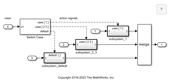
The Switch Case block selects the execution of one Switch Case Action Subsystem block from a set of subsystems. Regardless of which subsystem the Switch Case block selects, you can create one resulting signal with a Merge block.
The input to the Switch Case block provides the index value for selecting a case represented as output ports. Each output port is attached to a Switch Case Action Subsystem block. When a case is selected, its corresponding Switch Case Action Subsystem block is executed.
The switch structure in the model can be represented with this pseudo code.
CASE u1
    u1 = 1:
        subsystem_1
        break
    u1 = 2 or 3:
        subsystem_2_3
        break
    u1 = OTHER VALUES:
        subsystem_default
        break
END CASE
Create Model with Switch Case Structure
To create the example model, use this procedure.
Place a Switch Case block in the Simulink Editor. Double-click the block to open the block parameters dialog box.
In the Case conditions box, enter
{1, [2,3]}.Two cases are defined. The first case when the input value is
1, and the second case when the input value is2or3. Cases can be single or multivalued and appear as output ports on the Switch Case block. Non-integer input values are truncated to integers.Select the Show default case check box.
An output port labeled
default:is added to the block. This port sends an action signal if no other cases are selected.Add three Switch Case Action Subsystem blocks.
These blocks are Subsystem blocks with an Action Port block. When you place an Action Port block inside a subsystem, an input port named Action is added to the block.
Connect each output port from the Switch Case block to the action port of an Switch Case Action Subsystem block.
When you make the connection, the icon for the Switch Case Action Subsystem block is renamed to the type of expression attached to it.
In each Switch Case Action Subsystem block, enter the Simulink blocks to be executed for the case it handles.
Run a simulation.
The action signal lines between the Switch Case block and the Switch Case Action Subsystem blocks change from a solid to a dashed line.
Note
After the subsystem for a particular case executes, an implied break terminates the
execution of the Switch Case block. Simulink
Switch Case blocks do not exhibit the fall -through behavior of C
switch statements.
See Also
Action Port | If | If Action Subsystem | Subsystem | Switch Case | Switch Case Action Subsystem