Remove Algebraic Loops
Use these techniques to remove algebraic loops in a model.
Remove Algebraic Loops by Introducing Delay
Feedback loops can create algebraic loops in a model. You can remove these algebraic loops by introducing a delay in the loop using the Unit Delay block.
Open the model AlgebraicLoopUnitDelay. The model contains three atomic subsystems, A, B, and C. The output from subsystem A is an input for subsystem B, and the output from subsystem B is an input for subsystem C. The output from subsystem C feeds back into subsystem A and subsystem B, creating two feedback loops.
mdl = "AlgebraicLoop";
open_system(mdl)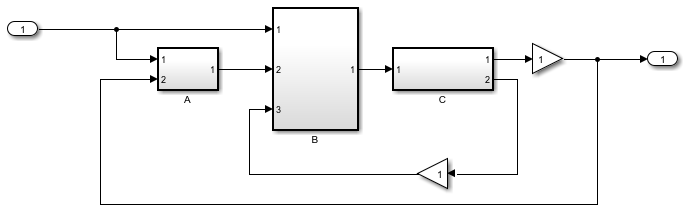
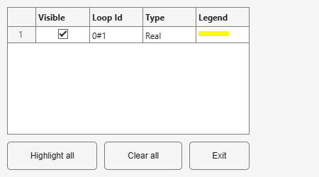
To determine whether the model contains algebraic loops, use the Simulink.BlockDiagram.getAlgebraicLoops function. The function opens the Algebraic Loops viewer, which shows that the model contains one real algebraic loop.
Simulink.BlockDiagram.getAlgebraicLoops(mdl);
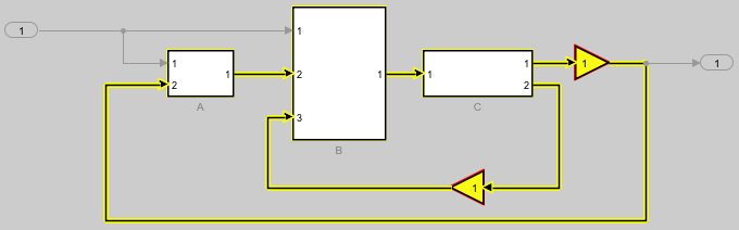
The Simulink.BlockDiagram.getAlgebraicLoops function highlights the path of the algebraic loop in the model in yellow and highlights blocks with algebraic variables in red. In the model AlgebraicLoop, the Gain blocks in the feedback loops are both highlighted as algebraic variables.
In general, to remove algebraic loops from your model, add a delay before or after each algebraic variable. To see this solution, open the model AlgebraicLoopTwoUnitDelays which is the same as the model AlgebraicLoop but with a Unit Delay block added after the Gain block in each feedback loop.
mdl2 = "AlgebraicLoopTwoUnitDelays";
open_system(mdl2)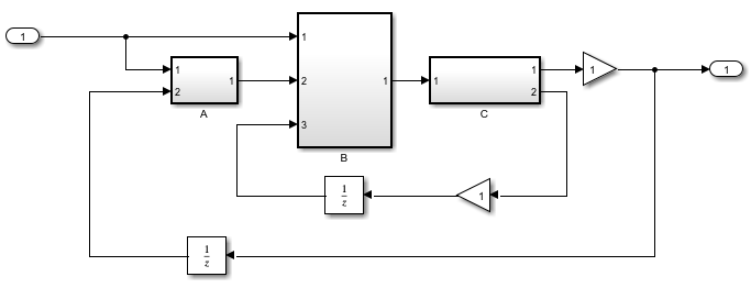
To confirm that the Unit Delay blocks removed the algebraic loops, use the Simulink.BlockDiagram.getAlgebraicLoops function.
Simulink.BlockDiagram.getAlgebraicLoops(mdl2);
No algebraic loops were found.
With this placement of Unit Delay blocks, subsystem A and subsystem B use the output from subsystem C from the previous time step.
In this model, you can also remove the algebraic loop by adding a single Unit Delay block between subsystem B and subsystem C. This signal path is part of both feedback loops, so the delay affects the path of both algebraic variables. To see this solution, open the model AlgebraicLoopOneUnitDelay.
mdl3 = "AlgebraicLoopOneUnitDelay";
open_system(mdl3)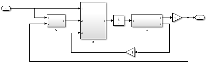
To confirm that the model does not contain an algebraic loop, use the Simulink.BlockDiagram.getAlgebraicLoops function.
Simulink.BlockDiagram.getAlgebraicLoops(mdl3);
No algebraic loops were found.
With this placement of the Unit Delay block, subsystem C uses the value from the previous time step for the output from subsystem B to produce the feedback value for the current time step.
Solve Algebraic Loops Manually
If the solver is unable to solve the algebraic loop, the software issues an error. Use one of these techniques to solve the loop manually:
Restructure the underlying DAEs using techniques such as differentiation or change of coordinates. These techniques put the DAEs in a form that is easier for the algebraic loop solver to solve.
Convert the DAEs to ODEs, which eliminates any algebraic loops.
Only for a legitimate algebraic loop, specify an initial guess for the algebraic states in the loop to help the algebraic loop solver converge. You can specify the initial guess one of these ways:
Place an IC block in the algebraic loop.
Specify an initial guess for a signal in an algebraic loop using an Algebraic Constraint block.
Minimize Artificial Algebraic Loop Occurrences
Artificial algebraic loops occur as a result of model and
software architecture and do not correspond to real algebraic constraints in the system
equations. For example, model references and atomic subsystems can both create
artificial algebraic loops because they execute as atomic units, which means that they
have a single Outputs method. The single Outputs
method computes output values for all output ports of the model or subsystem. The
software flags a model reference or atomic subsystem as having direct feedthrough if the
value of any output port depends on the value of any input port. An artificial algebraic
loop occurs when a Model block or atomic subsystem is flagged as having
direct feedthrough and the direct feedthrough path is not part of or connected to the
loop.
While the software cannot eliminate all artificial algebraic loops without more significant modifications to the model, both referenced models and atomic subsystems have a parameter you can enable to minimize artificial algebraic loops that involve that model or subsystem. The way to minimize artificial algebraic loop occurrences depends on whether a referenced model or atomic subsystem creates the loop.
| Source of Artificial Algebraic Loop | Enable Minimize artificial algebraic loop occurrences Parameter |
|---|---|
| Referenced model |
|
| Atomic subsystem |
|
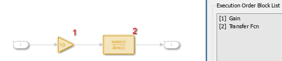
When you enable the Minimize artificial algebraic loop occurrences parameter, the software tries to eliminate artificial algebraic loops that involve the referenced model or atomic subsystem by compiling the model or subsystem with a different execution order. For example, consider this model, which contains an atomic subsystem that creates an artificial algebraic loop. The dotted line in the algebraic loop highlighting indicates that the loop is artificial.
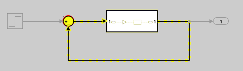
The subsystem input port connects to a Gain block, which connects to a Transfer Fcn block. The Transfer Fcn block connects to the subsystem output port. Because the Transfer Fcn block does not have direct feedthrough, the atomic subsystem does not contain a direct feedthrough path from the input port to the output port. The loop is artificial because the subsystem contents do not have direct feedthrough, but the software flags the atomic system as having direct feedthrough.
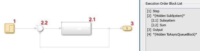
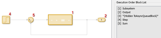
You can see the effect of enabling the Minimize artificial algebraic loop occurrences parameter for this atomic subsystem by viewing the execution order of the model before and after enabling the parameter. With the Minimize artificial algebraic loop occurrences parameter of the atomic subsystem disabled, the software executes the Step block first and inserts a hidden subsystem that contains the atomic subsystem and the Sum block to solve the artificial algebraic loop.
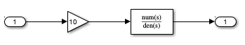
To view the order in which the atomic subsystem contents execute, navigate inside the atomic subsystem. The atomic subsystem executes the Gain block first and the Transfer Fcn block second.
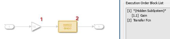
With the Minimize artificial algebraic loop occurrences parameter of the atomic subsystem enabled, the execution order of the model changes. In the top level of the model that contains the atomic subsystem, the artificial algebraic loop no longer exists, so the software does not insert a hidden subsystem to solve the artificial algebraic loop. Instead of executing the Step block first, the software executes the Subsystem block first.
Inside the atomic subsystem, the software inserts a hidden subsystem that contains blocks between the input port in the artificial algebraic loop and the first block that does not have direct feedthrough in the path to the output port in the artificial algebraic loop. In this model, the hidden subsystem contains the Gain block. With the Minimize artificial algebraic loops parameter enabled, the software determines an execution order that eliminates the output dependency that created the artificial algebraic loop.
Identify Unresolved Artificial Algebraic Loops
In some cases, the software cannot eliminate the dependencies in the
Output method that create artificial algebraic loops. For
example, the software is unable to remove artificial algebraic loops if:
A signal in a direct feedthrough path that is part of the artificial algebraic loop is designated as a test point in the referenced model or atomic subsystem.
An input port that is part of the artificial algebraic loop has a direct feedthrough path to an output port that is not part of the loop.
Before R2026a: A signal in a direct feedthrough path that is part of the artificial algebraic loop is marked for logging in the referenced model or atomic subsystem.
If an input port that is part of the algebraic loop has a direct feedthrough path to an output port that is part of the loop, then the loop is not artificial.
By default, the software issues a warning if a referenced model or atomic subsystem that enables the Minimize artificial algebraic loop occurrences parameter is part of an artificial algebraic loop that the software cannot eliminate. You can configure the model to issue an error or to issue no diagnostic in this situation using the Artificial algebraic loop occurrences not eliminated configuration parameter.
Remove Unresolved Artificial Algebraic Loops Caused by Atomic Subsystems
If the software is unable to eliminate artificial algebraic loops that involve an atomic subsystem, you can eliminate the artificial algebraic loop by making the subsystem virtual instead of atomic. Converting a subsystem from atomic to virtual changes the way the subsystem contents execute during simulation. For more information, see Specify Whether Subsystem Is Atomic and Virtual and Nonvirtual Subsystems.
To convert an atomic subsystem to a virtual subsystem:
Open the model that contains the atomic subsystem.
Right-click the atomic subsystem and clear Is Atomic.
Save the changes.
Bundled Signals That Create Artificial Algebraic Loops
Some models bundle signals together. This bundling can cause Simulink to detect an algebraic loop, even when an algebraic constraint does not exist. If you redirect one or more signals, you may be able to remove the artificial algebraic loop.
In this example, a linearized model simulates the dynamics of a two-tank system fed by a single pump. In this model:
Output
q1is the rate of the fluid flow into the tank from the pump.Output
h2is the height of the fluid in the second tank.The State-Space block defines the dynamic response of the tank system to the pump operation:
The output from the State-Space block is a vector that contains
q1andh2.
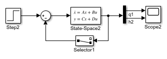
If you simulate this model with the Algebraic loop parameter set
to warn or error, Simulink identifies the algebraic loop.
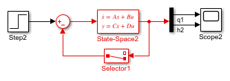
To eliminate this algebraic loop:
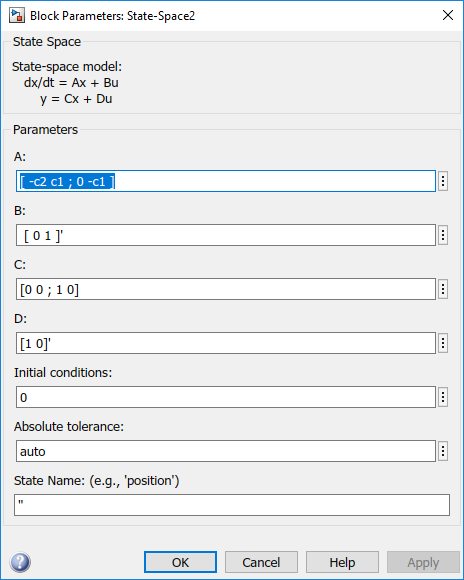
Change the
CandDmatrices as follows: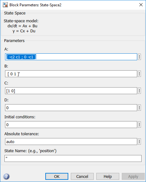
Pass
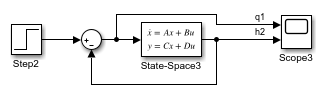
q1directly to the Scope instead of through the State-Space block.Now, the input (
q1) does not pass directly to the output (theDmatrix is 0), so the State-Space block no longer has direct feedthrough. The feedback signal has only one element now, so the Selector block is no longer necessary, as you can see in the following model.
Block Reduction and Artificial Algebraic Loops
When you enable the Block reduction optimization in Model Configuration Parameters, Simulink collapses certain groups of blocks into a single, more efficient block, or removes them entirely. Enabling block reduction results in faster execution during model simulation and in generating code.
Enabling block reduction can also help Simulink solve artificial algebraic loops.
Consider the following model.
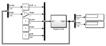
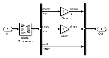
Initially, block reduction is turned off. When you simulate this model, the Atomic Unit subsystem and Gain and Compare to Constant blocks are part of an algebraic loop that Simulink cannot solve.
If you enable block reduction and execution order, and simulate the model again, Simulink does not display the execution order for blocks that have been reduced. You can now quickly see which blocks have been reduced.
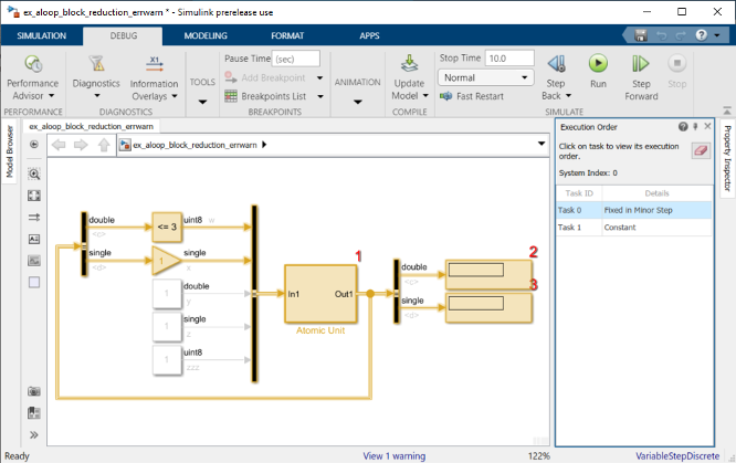
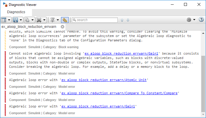
The Compare to Constant and Gain blocks have been eliminated from the model, so they no longer generate an algebraic loop error. The Atomic Unit subsystem generates a warning:
Warning: If the inport 'ex_aloop_block_reduction_errwarn/
Atomic Unit/In1' of subsystem 'ex_aloop_block_reduction_errwarn/
Atomic Unit' involves direct feedback, then an algebraic loop
exists, which Simulink cannot remove. Consider clearing the
'Minimize artificial algebraic loop occurrences' parameter to avoid this
warning.
Tip
Use Bus Selector blocks to pass only the required signals into atomic subsystems.
See Also
Blocks
Model Settings
- Minimize artificial algebraic loop occurrences | Artificial algebraic loop occurrences not eliminated