Define Subsystem Reference Interfaces Using Test Harnesses and Generate Reusable Code
This example shows you how to define interfaces for a subsystem reference component using test harnesses and verify that the model reuses the component in defined interfaces only. It also shows how you can generate code for the subsystem reference component and reuse it in a model.
Subsystem Reference components adapt to the environment in which they are used. As a result, you might get undesired results when you use a subsystem reference component in an untested environment. To ensure pertinent results, you can mark the test harnesses of a subsystem file that produce the intended results as unit tests.
Use the Unit Test features available in the Simulink® toolstrip to:
Specify valid testing environments of a subsystem file.
Capture signatures to diagnose and resolve invalid use of components.
Generate code for components to reuse in the top model.
Video Walkthrough
For a walkthrough of the example, play the video.
Validate Subsystem Reference Use in Model and Generate Reusable Code
Explore the Model
1. Open the subsystem file slexReusableSS.
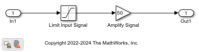
The subsystem slexReusableSS limits the input between (-10,10) and then amplifies the result by a factor of 50. slexReusableSS has two test harnesses, ssref1_double and ssref1_int32. To accommodate data between (-500,500), ssref1_double and ssref1_int32 use double and int32 data types, respectively.
2. Open the model slexModelUsingReusableSS.
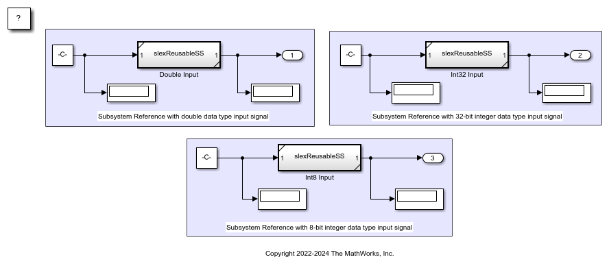
The model slexModelUsingReusableSS uses three instances of the subsystem file slexReusableSS named Double Input, Int32 Input2, and Int8 Input. The inputs to Double Input, Int32 Input, and Int8 Input are constants of type double, int32, and int8, respectively.
Define Interfaces and Verify Component Use
This section explains how to validate the use of Subsystem Reference blocks Double Input, Int32 Input2, and Int8 Input in the model slexModelUsingReusableSS using unit test features.
1. In the subsystem file slexReusableSS, select the test harnesses ssref1_double and ssref1_int32 from the drop-down menu of the Select unit tests button on the Simulink® toolstrip.
If you create new test harnesses for the subsystem file, set the Subsystem Reference block in the test harness as Atomic with Reusable function packaging.
2. To generate signatures, select Generate Signature option from the Generate Signature menu on the Simulink® toolstrip. This action generates signatures for the Subsystem Reference block in the unit tests ssref1_double and ssref1_int32 of the subsystem file.
Alternatively, in complex subsystems, you can generate signatures for the selected unit tests in parallel using multiple instances of MATLAB®. This approach enables you to speed up signature generation. For more information, see Get Started with Parallel Computing Toolbox (Parallel Computing Toolbox). To generate signatures in parallel, run the MATLAB® script generateSignatureInParallel.m. The script performs the following steps:
Load subsystem file and unit tests.
Set up parallel computing.
Generate signatures in parallel using multiple MATLAB® sessions.
Save signatures in subsystem file.
3. Save the subsystem file slexReusableSS.
4. To verify use of subsystem reference instances in the model, simulate the model slexModelUsingReusableSS. Simulink® compares the signatures of the Subsystem Reference blocks Double Input, Int32 Input2, and Int8 Input in the model with the signatures of the Subsystem Reference block in the unit tests ssref1_double and ssref1_int32. Use of a subsystem reference is valid when its signature matches at least one unit test signature.
5. Diagnostic Viewer displays an error message to highlight the invalid use of the subsystem reference Int8 Input in the model as Int8 Input does not have matching signature with any of the unit tests.
To disable the error message, set the diagnostic parameter Behavior when a matching unit test for subsystem reference is missing to none or warning in the Configuration Parameters dialog box.
Alternatively, use the Signature Difference Viewer to identify the reason for the signature mismatch and resolve these differences. The Signature Difference Viewer box provides parsed differences between the attributes of the Subsystem Reference block Int8 Input in the model and the attributes of the Subsystem Reference block in the test harnesses ssref1_double and ssref1_int32 of slexReusableSS.
6. Resolve the diagnostic messages and run the model slexModelUsingReusableSS again.
Generate Code
This section explains how to generate code for the Subsystem Reference block in the test harnesses ssref1_double and ssref1_int32.
1. In the subsystem file slexReusableSS, open test harness ssref1_double and go to Model Settings > Code Generation > Interface and set Shared code placement to Shared location. This action sets a common location to save generated codes. For more information, see Shared code placement (Simulink Coder). Save test harness ssref1_double and apply the same setting to the other test harness ssref1_int32.
2. To generate code, select the Generate Code option from the Generate Signature menu on the Simulink® toolstrip. This action generates code for the Subsystem Reference block in the selected test harnesses ssref1_double and ssref1_int32.
3. Save slexReusableSS.
Reuse Code
This section explains how you can reuse the generated code of the Subsystem Reference block to build the model.
1. Set the code generation folder structure using Simulink.fileGenControl (Simulink Coder).
Simulink.fileGenControl('set','CodeGenFolderStructure',...
Simulink.filegen.CodeGenFolderStructure.TargetEnvironmentSubfolder);
2. Press Command + B on Mac or Ctrl + B on all other operating systems to build the model slexModelUsingReusableSS.
In the build, the model slexModelUsingReusableSS uses the code generated for subsystem reference slexReusableSS. To check the reused codes, open the code generation report for the model.
See Also
Blocks
Functions
Simulink.SubsystemReference.generateSignatures|Simulink.SubsystemReference.getUnitTestNames|Simulink.SubsystemReference.removeSignatures|Simulink.SubsystemReference.showSignatureDiffDialogForSS|Simulink.SubsystemReference.showSignatureDiffDialogForUnitTests