Pin Mapping for Arduino Timer-Dependent Blocks
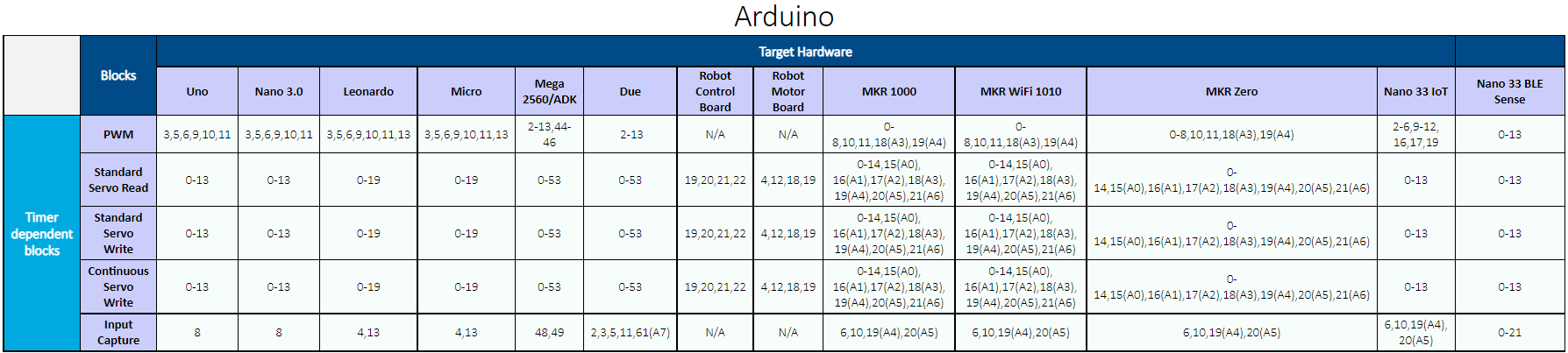
Simulink® Support Package for Arduino® Hardware supports these blocks whose operation is dependent on the timer of the Arduino hardware board.
To view the pin mapping for these blocks, click View pin map in
the Block Parameters dialog box. This opens the pin mapping table for Arduino boards and Arduino compatible ESP32 boards. For example, to find which pins you can use in
the Standard Servo Write block for the Uno
board, look for the Standard Servo Write entry under the
Blocks column vertically down and Uno
board horizontally across. Pins 0-13 can be used
for the Uno board.
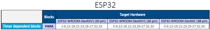
For ESP32-WROOM and ESP32-WROVER Arduino compatible boards, use the following pin mapping table to enter the pin numbers for the timer dependent blocks in the Simulink model.
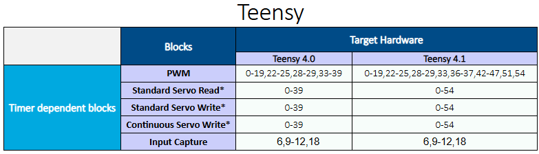
For Teensy 4.0 and 4.1 Arduino compatible boards, use the following pin mapping table to enter the pin numbers for the timer dependent blocks in the Simulink model.
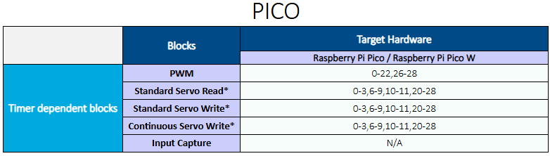
For Raspberry Pi® Pico and Pico W Arduino compatible boards, use the following pin mapping table to enter the pin numbers for the timer dependent blocks in the Simulink model.
Conflicting Pin Configurations on Arduino Timer
Use one Arduino timer for only one block functionality at a time. For example, if your model uses the PWM block, you cannot connect the Input Capture and Servo blocks to the same timer. Similarly, if your model uses the Input Capture block, you cannot connect the PWM and Servo blocks to the same timer. And, if your model uses the Servo blocks, you cannot connect the PWM and Input Capture blocks to the same timer.
If your Simulink model utilizes multiple timer-dependent blocks, you can use the following table to avoid timer conflicts.
| Arduino Board | Arduino Timer | Arduino Pin Connections for Input Capture Block | Arduino Pin Connections for PWM Block | Servo Block Usage Conflict |
|---|---|---|---|---|
| Uno, Nano 3.0 | Timer 1 | 8 | 9, 10 | Set 1 |
| Mega 2560/ADK | Timer 5 | 48 | 44, 45,
46 | Set 1 |
| Timer 1 | NA | 11, 12 | Set 2 | |
| Timer 3 | NA | 2, 3,
5 | Set 3 | |
| Timer 4 | 49 | 6, 7,
8 | Set 4 | |
| Leonardo, Robot Control Board, Robot Motor Board, Micro | Timer 1 | 4 | 9, 10 | Set 1 |
| Timer 4 | 13 | 6, 13 | NA | |
| MKR 1000, MKR Wifi 1010, MKR Zero | Timer TCC0 | 10 | 6, 7,
11, 18 (A3),
19 (A4) | NA |
| Timer TCC1 | 6 | 2, 3 | NA | |
| Timer TCC2 | 19 (A4) | 8 | NA | |
| Timer TC3 | 20 | 0, 1 | Set 1 | |
| Timer TC4 | 10 | NA | ||
| Nano 33 IoT | Timer TCC0 | 10 | 5, 6, 9,
10, 16,
17 | NA |
| Timer TCC1 | 6 | 4 | NA | |
| Timer TCC2 | 19 | 11 | NA | |
| Timer TC3 | 20 | 12 | NA | |
| Timer TC4 | 19 | Set 1 | ||
| Due | Timer TC0_CH0 | 2 | 2, 13 | NA |
| Timer TC2_CH2 | 11 | NA | Set 4 |
Consider these example combinations for different Arduino boards:
For the Arduino Leonardo board, if your Simulink model uses the Input Capture block that is connected to pin number 4, then you cannot connect the PWM block to pin number 9 and 10, and you cannot use Servo blocks in the model.
For the Arduino Nano 33 IoT board, if your Simulink model uses the Input Capture block that is connected to pin number 10, then you cannot connect the PWM block to pin numbers 5, 6, 9, 10, 16, and 17.
Supported Default PWM Frequencies and Pins on Arduino Compatible Teensy Boards
Use this table to configure the PWM block in your Simulink model and map the default PWM frequencies with the hardware pins on your Arduino compatible Teensy boards.
| Arduino Compatible Board | Timer | PWM Pins | PWM Default Frequencies | Input Capture Pins |
|---|---|---|---|---|
| Teensy 4.1 | FlexPWM1.0 | 1, 44, 45 | 4.482 kHz | NA |
| FlexPWM1.1 | 0, 42, 43 | |||
| FlexPWM1.2 | 24, 46, 47 | |||
| FlexPWM1.3 | 7, 8, 25 | |||
| FlexPWM2.0 | 4, 33 | |||
| FlexPWM2.1 | 5 | |||
| FlexPWM2.2 | 6, 9 | |||
| FlexPWM2.3 | 36, 37 | |||
| FlexPWM3.0 | 54 | |||
| FlexPWM3.1 | 28, 29 | |||
| FlexPWM3.3 | 51 | |||
| FlexPWM4.0 | 22 | |||
| FlexPWM4.1 | 23 | |||
| FlexPWM4.2 | 2, 3 | |||
| QuadTimer1.0 | 10 | 3.611 kHz | 10 | |
| QuadTimer1.1 | 12 | 12 | ||
| QuadTimer1.2 | 11 | 11 | ||
| QuadTimer2.0 | 13 | NA | ||
| QuadTimer3.0 | 19 | NA | ||
| QuadTimer3.1 | 18 | 18 | ||
| QuadTimer3.2 | 14 | NA | ||
| QuadTimer3.3 | 15 | NA | ||
| QuadTimer4.1 | NA | 6 | ||
| QuadTimer4.2 | NA | 9 | ||
| Teensy 4.0 | FlexPWM1.0 | 1, 36, 37 | 4.482 kHz | NA |
| FlexPWM1.1 | 0, 34, 35 | |||
| FlexPWM1.2 | 24, 38, 39 | |||
| FlexPWM1.3 | 7, 8, 25 | |||
| FlexPWM2.0 | 4, 33 | |||
| FlexPWM2.1 | 5 | |||
| FlexPWM2.2 | 6, 9 | |||
| FlexPWM3.1 | 28, 29 | |||
| FlexPWM4.0 | 22 | |||
| FlexPWM4.1 | 23 | |||
| FlexPWM4.2 | 2, 3 | |||
| QuadTimer1.0 | 10 | 3.611 kHz | 10 | |
| QuadTimer1.1 | 12 | 12 | ||
| QuadTimer1.2 | 11 | 11 | ||
| QuadTimer2.0 | 13 | NA | ||
| QuadTimer3.0 | 19 | NA | ||
| QuadTimer3.1 | 18 | 18 | ||
| QuadTimer3.2 | 14 | NA | ||
| QuadTimer3.3 | 15 | NA | ||
| QuadTimer4.1 | NA | 6 | ||
| QuadTimer4.2 | NA | 9 |
The following table provides the maximum frequency that the PWM block generates in your Simulink model for an 8-bit resolution input data.
| Arduino Compatible Board | Input Data Resolution | PWM Value | Generated PWM Output Frequency (Hz) for CPU Speeds: 600 MHz, 450 MHz | Generated PWM Output Frequency (Hz) for CPU Speeds: 528 MHz, 396 MHz | Generated PWM Output Frequency (Hz) for CPU Speeds: 24 MHz |
|---|---|---|---|---|---|
| Teensy 4.0 and 4.1 | 8 | 0–255 | 585937.5 | 515625 | 93750 |
See Also
Pin Mapping for Arduino Timer-Independent Blocks | Supported Arduino Hardware