Hardware Interrupt
Trigger downstream function-call subsystems from interrupt service routine for Arduino SAMD21 core
Since R2023b
Libraries:
Simulink Support Package for Arduino Hardware /
Advanced /
SAMD
Description
Add-On Required: This feature requires the Simulink Support Package for Arduino Hardware add-on.
Use the Hardware Interrupt block to create an interrupt service routine (ISR) automatically in the generated code of your Simulink® model for the selected interrupts. The ISR executes the downstream function-call subsystem associated with event ports of the block.
The function call subsystem associated with the event output port run at the same priority as the ISR.
Using this block, you can:
Create an ISR on the Arduino® board.
Set priority for an ISR.
Enable or disable interrupt preemption.
This block generates code only for the ISR and events that you select or specify. To change the configuration, enable the interrupt, and specify triggering options, use the settings of the selected peripherals.
To create an ISR for the ADC peripheral on the Hardware Interrupt block:
Your Simulink model must have an Analog Input block. In the block, select the Enable end of conversion interrupt parameter.
In the Hardware Interrupt block, set these parameters:
Interrupt group to
Analog to digital
                    converter
Interrupt name to
ADC_HandlerEvents to serve to
ADC RESRDYorADC OVERRUN
To create an ISR for the PWM peripheral on the Hardware Interrupt block:
Your Simulink model must have a PWM block. In the block, select the Enable compare match (MCx) interrupt or Enable overflow/underflow (OVF) interrupt parameter or both the parameters.
In the Hardware Interrupt block, set these parameters:
Interrupt group to
Timer/Counter for Control Applications (TCC).Interrupt name to either
TCC0_Handler,TCC1_Handler, orTCC2_Handler.Events to serve to
TCCx overflow,TCCx MCx.
To create an ISR for the SERCOM peripheral on the Hardware Interrupt block:
Your Simulink model must have a Serial Transmit or Serial Receive blocks, select the Enable transmit complete interrupt, Enable receiver error interrupt, or Enable receive complete interrupt parameters or all the parameters.
In the Hardware Interrupt block, set these parameters:
Interrupt group to either
Sercom0 Serial Interrupts,Sercom2 Serial Interrupts,Sercom3 Serial Interrupts, orSercom4 Serial Interrupts.Interrupt name to either
SERCOM0_Handler,SERCOM2_Handler,SERCOM3_Handler, orSERCOM4_Handler.Events to serve to
SERCOM Tx Complete,SERCOM Rx Complete, andSERCOM Rx Error.
Note
The Hardware Interrupt block supports C/C++ code generation. This feature allows you to generate C and C++ code using Embedded Coder®.
Supported Arduino Boards
Arduino MKR 1000
Arduino MKR ZERO
Arduino MKR Wi-Fi® 1010
Arduino Nano 33 IoT
Examples
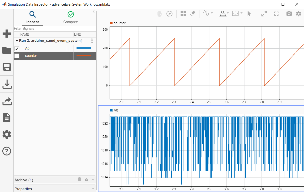
Get Started with Arduino SAMD Event System Using PWM and ADC Peripherals
Use the event system with Arduino Advanced PWM, Analog Input, and Hardware Interrupt blocks.
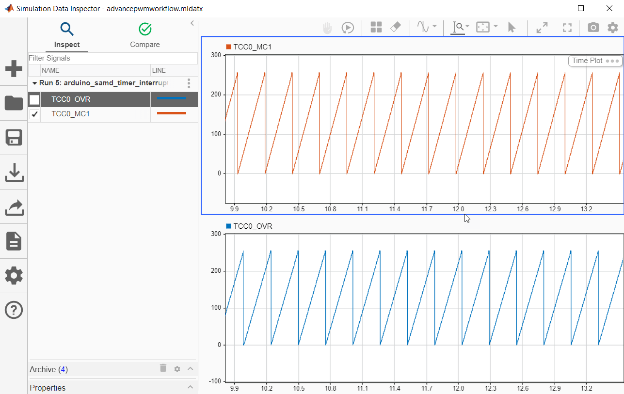
Generate Interrupts Using Arduino SAMD PWM Block
Use the Hardware Interrupt block to create an interrupt service routine (ISR) to react to the PWM events on your Arduino® hardware.
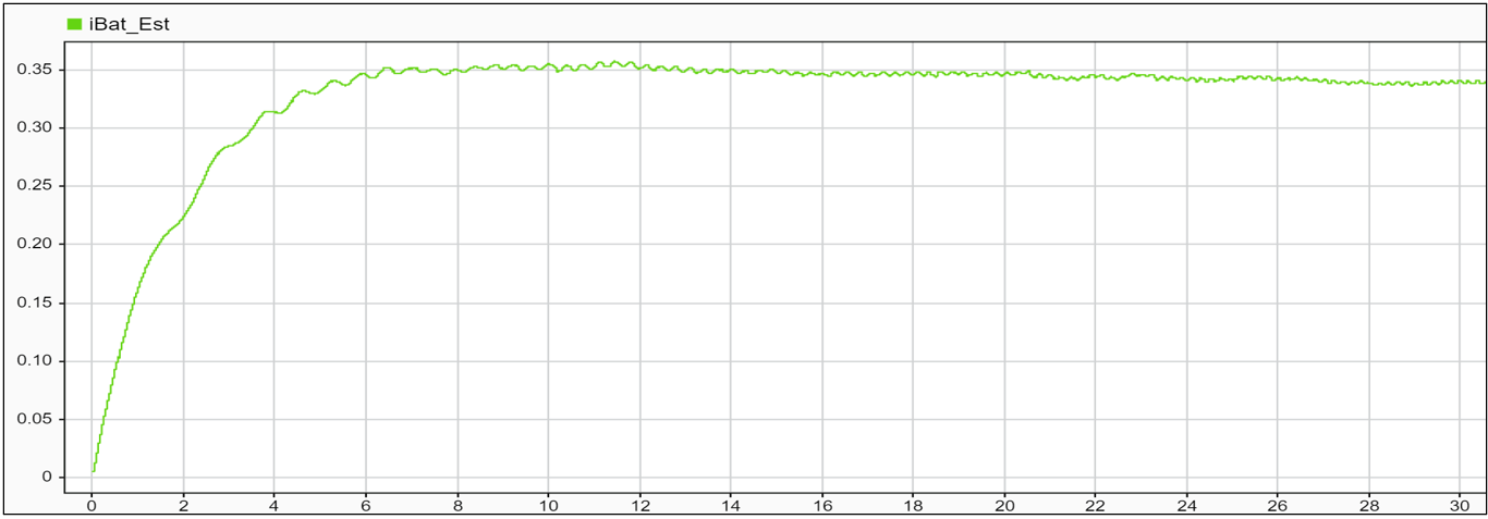
Estimate Battery Current of PMSM in Open-Loop Control Using Arduino Hardware
Use Simulink® Support Package for Arduino® Hardware to estimate the battery current of a permanent magnet synchronous machine (PMSM) in open-loop control using Motor Control Blockset™. This example also shows how to actuate a PMSM motor and calculate phase currents that are indirectly used to estimate the current of the battery.
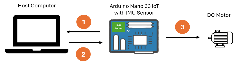
IMU-Based Motor Speed Control on Arduino Using SERCOM Serial Interrupts
Learn how to implement motor speed control on Arduino using IMU sensor data and SERCOM serial interrupts in Simulink.
Ports
Output
Parameters
Version History
Introduced in R2023b