Implement Block Algorithms Using MATLAB System Object and MATLAB System Block
This example shows how to use a MATLAB System block to implement an algorithm that generates Pulse Width Modulation (PWM) signal. The PWM signal algorithm is implemented using a MATLAB® System object™. The MATLAB System block integrates the system object into the Simulink® environment. In this example, you can set the duty cycle and frequency interactively to generate different PWM signals.
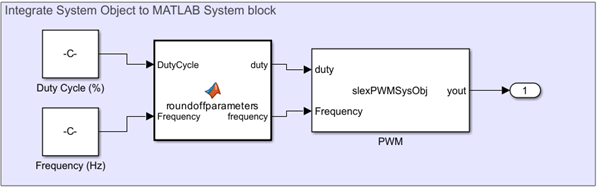
Interface MATLAB System Object with MATLAB System Block
The MATLAB System block uses the System object slexPWMSysObj to generate a PWM signal. The block accepts the duty cycle and signal frequency at its input ports. Additionally, the block also has two constant parameters, the amplitude of the generated PWM signal and the resolution of the controllable sample time. These constant parameters are defined as nontunable properties of the System object.
Define PWM Algorithm Using MATLAB System Object
The amplitude of the output PWM signal is defined using the stepImpl function inside the setNumTicksUntilNextHit method. The setNumTicksUntilNextHit method sets the number of ticks in the controllable sample time to wait until the next call to stepImpl. In this example, the number of ticks is computed using the duty cycle and frequency. The controllable sample time is defined using the createSampleTime function. The sample time resolution defines the fundamental step size of the MATLAB System block.
function yout = stepImpl(obj,duty,Frequency)
      f = Frequency;
      numSamples = floor(1/(obj.Resolution*f));
      numTicksToNextHit = floor((duty/100)*numSamples);
if (obj.IsHit)
           yout = obj.Amplitude;
           obj.IsHit = false;
else
           yout = 0;
           obj.IsHit = true;
           numTicksToNextHit = numSamples - numTicksToNextHit;
       end
setNumTicksUntilNextHit(obj, numTicksToNextHit);
end
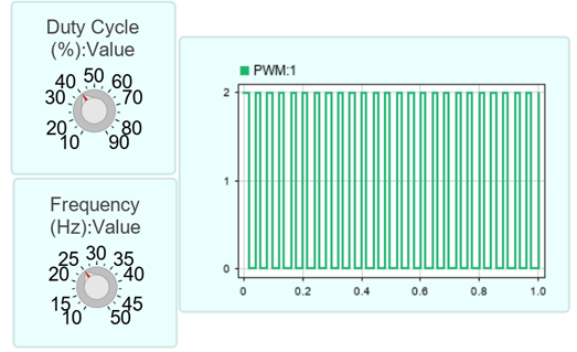
Simulate and Visualize Results
Simulate the model and visualize the results using a Scope block. This example generates a PWM signal of amplitude 2 with a 40% duty cycle at a frequency of 25 Hz. You can change the amplitude, duty cycle, and frequency values to generate different PWM signals per your requirement.