Bias
Add bias to input
Libraries:
Simulink /
Math Operations
HDL Coder /
HDL Floating Point Operations
HDL Coder /
Math Operations
Description
The Bias block adds a bias, or offset, to the input signal according to
Y = U + bias
where U is the block input and Y is the output.
Examples
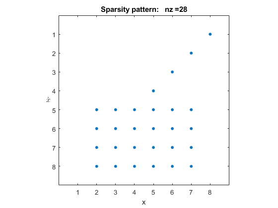
Exploring the Solver Jacobian Structure of a Model
The example shows how to use Simulink® to explore the solver Jacobian sparsity pattern, and the connection between the solver Jacobian sparsity pattern and the dependency between components of a physical system. A Simulink model that models the synchronization of three metronomes placed on a free moving base are used.
Ports
Input
Input signal to which the bias is added to create the output signal.
Data Types: half | single | double | int8 | int16 | int32 | int64 | uint8 | uint16 | uint32 | uint64 | fixed point
Output
Output signal resulting from adding the bias to the input signal.
Data Types: half | single | double | int8 | int16 | int32 | int64 | uint8 | uint16 | uint32 | uint64 | fixed point
Parameters
Specify the value of the offset to add to the input signal. The
Bias block implicitly adds
Bias to the input signal. To subtract
Bias from the signal, specify a negative value
whose data type can store a negative value.
Programmatic Use
Block Parameter:
Bias |
| Type: character vector |
| Values: real, finite |
Default:
'0.0' |
Specify whether overflows saturate or wrap.
on— Overflows saturate to either the minimum or maximum value that the data type can represent.off— Overflows wrap to the appropriate value that the data type can represent.
For example, the maximum value that the signed 8-bit integer int8
can represent is 127. Any block operation result greater than this maximum value causes
overflow of the 8-bit integer.
With this parameter selected, the block output saturates at 127. Similarly, the block output saturates at a minimum output value of -128.
With this parameter cleared, the software interprets the overflow-causing value as
int8, which can produce an unintended result. For example, a block result of 130 (binary 1000 0010) expressed asint8is -126.
Tips
Consider selecting this parameter when your model has a possible overflow and you want explicit saturation protection in the generated code.
Consider clearing this parameter when you want to optimize efficiency of your generated code. Clearing this parameter also helps you to avoid overspecifying how a block handles out-of-range signals. For more information, see Troubleshoot Signal Range Errors.
When you select this parameter, saturation applies to every internal operation on the block, not just the output or result.
In general, the code generation process can detect when overflow is not possible. In this case, the code generator does not produce saturation code.
Programmatic Use
To set the block parameter value programmatically, use
the set_param function.
| Parameter: | SaturateOnIntegerOverflow |
| Values: | 'off' (default) | 'on' |
Block Characteristics
Data Types |
|
Direct Feedthrough |
|
Multidimensional Signals |
|
Variable-Size Signals |
|
Zero-Crossing Detection |
|
More About
If you have a Simulink® Coverage™ license and you enable saturation on integer overflow coverage, the Bias block receives saturation on integer overflow coverage. To enable saturation on integer overflow coverage, in the Coverage pane of the Configuration Parameters dialog box, select the Saturation on integer overflow (Simulink Coverage) parameter. For more information, see Saturate on Integer Overflow Coverage (Simulink Coverage).
Extended Capabilities
C/C++ Code Generation
Generate C and C++ code using Simulink® Coder™.
HDL Coder™ provides additional configuration options that affect HDL implementation and synthesized logic.
This block has one default HDL architecture.
| ConstrainedOutputPipeline | Number of registers to place at
the outputs by moving existing delays within your design. Distributed
pipelining does not redistribute these registers. The default is
|
| InputPipeline | Number of input pipeline stages
to insert in the generated code. Distributed pipelining and constrained
output pipelining can move these registers. The default is
|
| OutputPipeline | Number of output pipeline stages
to insert in the generated code. Distributed pipelining and constrained
output pipelining can move these registers. The default is
|
PLC Code Generation
Generate Structured Text code using Simulink® PLC Coder™.
Fixed-Point Conversion
Design and simulate fixed-point systems using Fixed-Point Designer™.
Version History
Introduced before R2006a
MATLAB Command
You clicked a link that corresponds to this MATLAB command:
Run the command by entering it in the MATLAB Command Window. Web browsers do not support MATLAB commands.
Select a Web Site
Choose a web site to get translated content where available and see local events and offers. Based on your location, we recommend that you select: .
You can also select a web site from the following list
How to Get Best Site Performance
Select the China site (in Chinese or English) for best site performance. Other MathWorks country sites are not optimized for visits from your location.
Americas
- América Latina (Español)
- Canada (English)
- United States (English)
Europe
- Belgium (English)
- Denmark (English)
- Deutschland (Deutsch)
- España (Español)
- Finland (English)
- France (Français)
- Ireland (English)
- Italia (Italiano)
- Luxembourg (English)
- Netherlands (English)
- Norway (English)
- Österreich (Deutsch)
- Portugal (English)
- Sweden (English)
- Switzerland
- United Kingdom (English)
