Convert RF Blockset Blocks to RF PCB Blocks
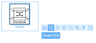
Simulate RF PCB components created from RF PCB Toolbox™ in the RF Blockset™ circuit envelope environment . To do so, click the Create PCB button located in Simulink action bar.
Use this workflow to simulate your RF system with RF PCB components such as couplers, dividers, and filters in a high-fidelity circuit envelope environment.
First, design the RF PCB components using a frequency-domain method of moments and other EM techniques in RF PCB Toolbox.
Second, inspect your RF system modeled in RF Blockset to identify the RF components that can be replaced with RF PCB components that you designed in the first step.
Finally, replace the identified RF components with RF PCB components.
To replace the identified RF components with RF PCB components in an RF Blockset model, you can either:
The RF PCB block enables you to create, visualize, and analyze the characteristics of the components used on a printed circuit board (PCB) in the RF Blockset circuit envelope simulation environment. You can create components like transmission lines, splitters, couplers, and baluns from the PCB Components Catalog (RF PCB Toolbox).
Note
To use this block, you need an RF PCB Toolbox license.
Analyze the RF PCB objects in the workspace for at least one frequency before using them in the block.
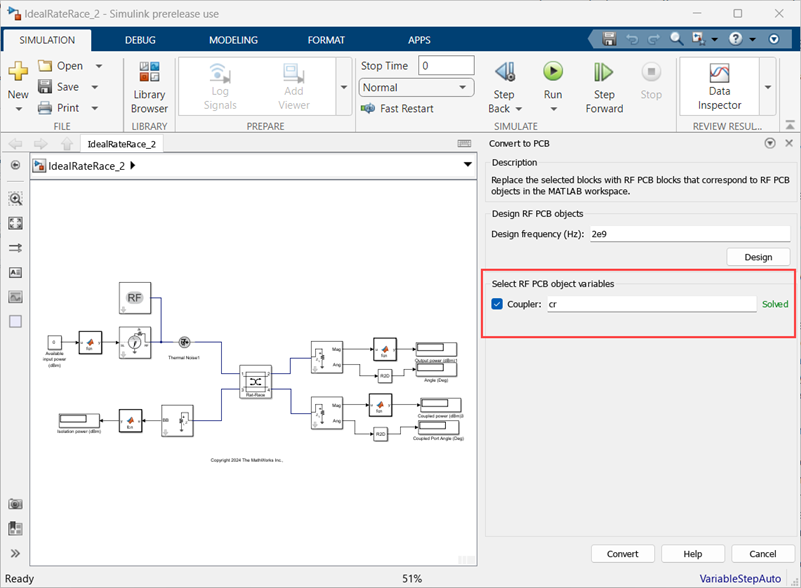
Convert Ideal Coupler to RF PCB Coupler
Use the Create PCB button to convert an RF component to RF PCB component. For example, replace an ideal coupler with an RF PCB coupler
First, create a rat-race coupler from a
couplerRatrace object using RF
PCB Toolbox. Then solve the object by calculating
its
S-parameters.
cr = couplerRatrace;
sparam = sparameters(cr,linspace(1e9,5e9,16));
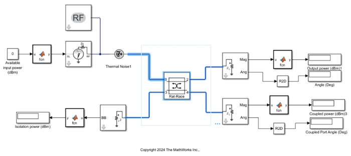
Create a copy of the
IdealRatRace.slx model from
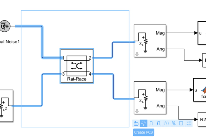
Ideal Coupler Vs. RF PCB Coupler example and select the Coupler block.
Select the Create PCB button from the Simulink action bar.
This opens a Convert to PCB window.
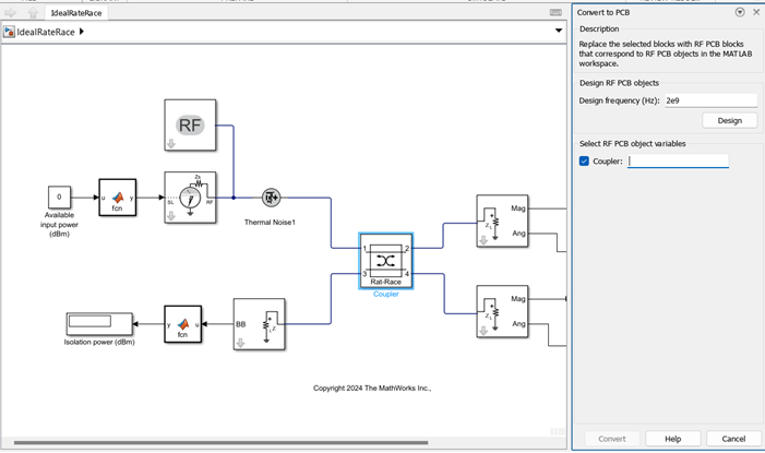
In the window that opens, enter the variable
name of the coupler object cr
that was created in the first step in
Select RF PCB object
variable.
Alternatively, if you have not created the RF PCB component object, then either first create an RF PCB component object at the command line or create the object using Convert to PCB window. To do so, first enter the design frequency of the component in Design frequency (Hz) and click Design.
Once you create the PCB object either at the command line or using Design button, click the Convert button to display the Convert Blocks to RF PCB dialog box.
Click the Convert button again to confirm your selection.
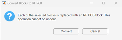
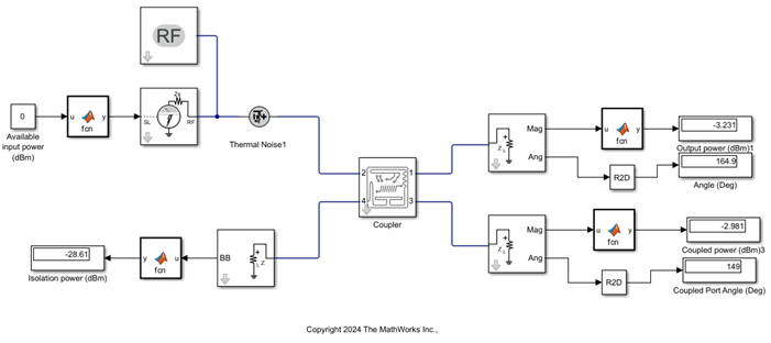
The Ideal coupler block is converted to an RF PCB block.
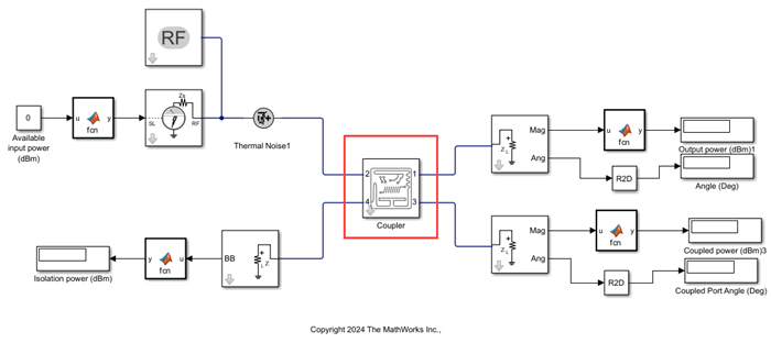
Simulate this rat-race model designed using the RF PCB block and observe the results at the output, coupling, and isolation ports.
Supported Blocks
The following blocks are supported for conversion using the Create PCB button:
Divider
Coupler
Phase Shifter
Transmission Line
Limitation
The following components are not supported for conversion using the Create PCB button:
Coaxial transmission line in Transmission Line block
Tee H-plane divider in the Divider block
Note
The Create PCB button will convert RF blocks into RF PCB blocks only if corresponding RF PCB objects from the RF PCB Toolbox exist that match the RF blocks from the Circuit Envelope Library.
The Design button is not supported to design:
Directional coupler, hybrid quadrature coupler, and hybrid rat-race coupler.
Resistive power divider, Tee H-plane divider, and Tee E-plane divider.
Types of transmission line except Delay-based Lossless.