Main Content

tdr

Characterize impedance discontinuities from S-parameters using TDR

Since R2025a

    Description

    Use time-domain reflectometry (TDR) to characterize impedance discontinuities from S-parameter data.

    Creation

    Description

    tdrObj = tdr(sparam) creates a TDR object from a Touchstone file or an sparameters object specified in sparam to characterize impedance discontinuities in a system.

    tdrObj = tdr(sparam,Name=Value) sets properties using one or more name-value arguments. For example, t = tdr(ConvertToDifferential=true) enables differential S-parameter conversion.

    example

    Input Arguments

    expand all

    N-port S-parameters, specified as either an sparameters object or an N-port Touchstone data file.

    Properties

    expand all

    Port definitions for single-ended and differential ports, specified as a vector of integers.

    • Single-ended ports: Define on which ports to perform TDR analysis by specifying the port indices in the vector.

    • Differential ports: Define the differential ports pairs by specifying the port indices in a vector of the form [DiffPort1p, DiffPort1n, DiffPort2p, DiffPort2n ...].

    Example: [1 2]

    Option to enable differential S-parameter conversion, specified as a logical true (1) or false (0). Set this property to true or 1 to enable differential S-parameter conversion.

    Example: true

    Time step of the TDR step response, specified as a positive scalar in seconds. The object uses sample time to define a default input signal and a custom TDR stimulus waveform that you specify using the CustomWaveform property.

    Example: 10e-3

    Rise time of the TDR step stimulus waveform, specified as a positive scalar in seconds.

    Example: 10e-12

    Stop time of the TDR step response, specified as a positive scalar in seconds.

    Example: 10e-8

    Custom TDR stimulus waveform, specified as a 1-D vector. Use this property to generate a custom TDR stimulus as an alternative to the default stimulus generated by this object. By default, the stimulus generated by this object is a step response with the default sample time, rise time, and end time.

    Note

    You must specify sample time in the SampleTime property when creating a custom TDR stimulus waveform using the CustomWaveform property.

    Example: [zeros(1,16),ones(1,16),zeros(1,128)], pulse response assuming 16 samples per symbol.

    Rational fitting options to control the rational object properties, specified as a structure.

    This object uses a rational object to perform rational fitting on complex frequency-dependent data. To do this, the object uses a noniterative interpolatory algorithm to construct a fit with complex frequencies. Input the properties and name-value arguments of the rational object to the structure to control the aspect of the fit. For more information on how to set this property, see Plot Differential TDR Response of a Specific Differential Port Pair.

    Example: struct('Tolerance',-30,'MaxPoles',500)

    This property is read-only.

    Fit of each TDR response, returned as a vectors of rational objects.

    This property is read-only.

    TDR response in units of impedance, returned as a column matrix.

    This property is read-only.

    TDR response in units of volts, returned as a column matrix.

    This property is read-only.

    Time vector corresponding to the TDR responses, returned as a vector.

    This property is read-only.

    IEEE quality rating for causality, reciprocity, and passivity for the input S-parameters, returned as a structure.

    This property is read-only.

    Port label for each TDR response, returned as a string array.

    Example: ["Port 1" "Port 2" "Port 3" "Port 4"]

    Object Functions

    createTDRTableReturn TDR results as MATLAB table
    plotPlot TDR response
    tdr.automaticPortOrderingDisplay port ordering of S-parameter data
    tdr.sParamQualityReturn S-parameter quality metrics

    Examples

    collapse all

    Create an S-parameter object from a 4-port Touchstone file.
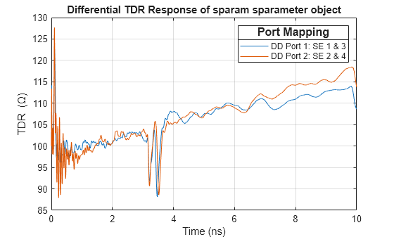
    sparam = sparameters('default.s4p');

    Create a TDR object and set the ConvertToDifferential property to true. In this example, the ports are not defined using the Ports property. Therefore, the tdr object automatically determines the differential ports.

    tdrObj = tdr(sparam,'ConvertToDifferential',true);

    Plot the differential TDR response of a 4-port S-parameter. This plot displays the port mapping between single-ended (SE) ports that the object identified as differential (DD) pairs.

    plot(tdrObj)

    Figure contains an axes object. The axes object with title Differential TDR Response of sparam sparameter object, xlabel Time (ns), ylabel TDR (\Omega) contains 2 objects of type line. These objects represent DD Port 1: SE 1 & 3 , DD Port 2: SE 2 & 4 .

    Use a 16-port S-parameter Touchstone file to plot the TDR response of a differential port pair located at port 1 and 2.

    First, create a structure to define the rational fitting parameters. These parameters enable you to control the rational fitting process for complex S-parameters.

    rationalOptions = struct('Tolerance',-30,'MaxPoles',500);

    Create a TDR object with the differential port pair set to 1 and 2.

    tdrObj = tdr('default.s16p',...
        ConvertToDifferential=true, ...
        Ports=[1 2],...
        EndTime=9e-9,...
        RiseTime=10e-12,...
        SampleTime=5e-12, ...
        RationalOptions=rationalOptions);

    Plot the differential TDR response of the differential port pair 1 and 2.

    plot(tdrObj)

    Figure contains an axes object. The axes object with title Differential TDR Response of default.s16p, xlabel Time (ns), ylabel TDR (\Omega) contains an object of type line. This object represents DD Port 1: SE 1 & 2 .

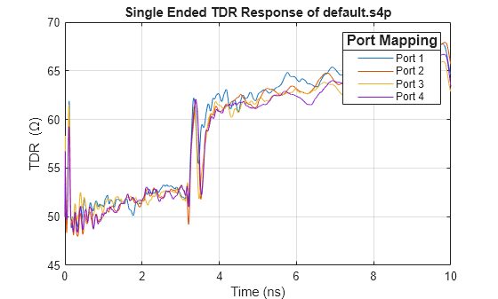
    Create a TDR object from a 4-port Touchstone file.

    tdrObj = tdr('default.s4p');

    Plot the single-ended TDR of a 4-port S-parameter in units of impedance.

    plot(tdrObj)

    Figure contains an axes object. The axes object with title Single Ended TDR Response of default.s4p, xlabel Time (ns), ylabel TDR (\Omega) contains 4 objects of type line. These objects represent Port 1, Port 2, Port 3, Port 4.

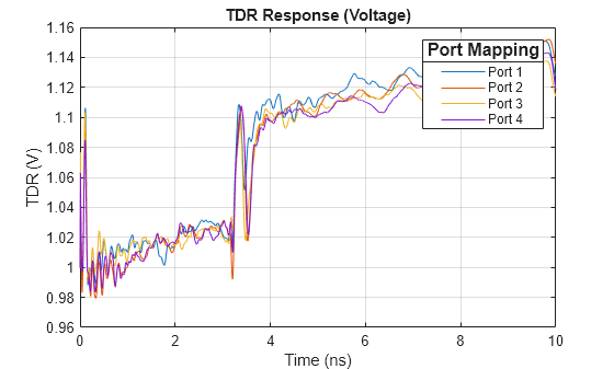
    Plot the single-ended TDR of a 4-port S-parameter in units of voltage.

    plot(tdrObj, Type="voltage", Title="TDR Response (Voltage)")

    Figure contains an axes object. The axes object with title TDR Response (Voltage), xlabel Time (ns), ylabel TDR (V) contains 4 objects of type line. These objects represent Port 1, Port 2, Port 3, Port 4.

    Plot the single-ended TDR of a 4-port S-parameter with respect to velocity of propagation of the medium. Scale the X-axis of this response in meters.

    plot(tdrObj,Vp=3e8/2,Title="TDR Response(m)")

    Figure contains an axes object. The axes object with title TDR Response(m), xlabel (m), ylabel TDR (\Omega) contains 4 objects of type line. These objects represent Port 1, Port 2, Port 3, Port 4.

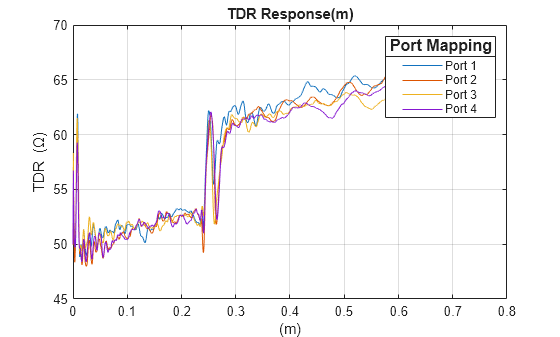
    Create a TDR table that displays the time and voltage TDR values for all the ports specified in the TDR object.

    T = createTDRTable(tdrObj,tdrType='voltage')
    T=10000×5 table
        Time (s)    Port 1 (V)    Port 2 (V)    Port 3 (V)    Port 4 (V)
        ________    __________    __________    __________    __________
    
              0            1             1             1             1  
          1e-12       1.0062       0.99943        1.0126        1.0087  
          2e-12        1.012       0.99992        1.0237        1.0168  
          3e-12       1.0175        1.0013        1.0335        1.0243  
          4e-12       1.0228        1.0035        1.0421        1.0312  
          5e-12       1.0278        1.0063        1.0498        1.0376  
          6e-12       1.0324        1.0097        1.0565        1.0436  
          7e-12       1.0369        1.0135        1.0625        1.0491  
          8e-12        1.041        1.0175        1.0678        1.0541  
          9e-12       1.0449        1.0218        1.0726        1.0587  
          1e-11       1.0485        1.0263        1.0769         1.063  
        1.1e-11       1.0457        1.0313        1.0682        1.0582  
        1.2e-11        1.043        1.0353        1.0606        1.0536  
        1.3e-11       1.0404        1.0382        1.0542        1.0494  
        1.4e-11       1.0378        1.0402        1.0487        1.0453  
        1.5e-11       1.0353        1.0414         1.044        1.0415  
          ⋮


    This example shows computation of time-domain reflectometry (TDR) and group delay of a coaxial transmission line.

    Design Coaxial Transmission Line

    Design a 75 Ω coaxial transmission line.

    Z0 = 75;            % Desired characteristic impedance (Ohms)
    innerRadius = 0.0005;   % Inner conductor radius (meters)
    dc = DielectricCatalog;
    ItemsDC = string(dc.Materials.Name);
    MaterialType = dielectric(ItemsDC(5)); % Low loss material

    Compute the outer radius of the cable from impedance:

    Z0=60εr*log(Dd)

    outerRadius = innerRadius*exp(Z0*sqrt(MaterialType.EpsilonR)/60);
    length = 0.01;        % Conductor length (meters)
    mc = MetalCatalog;
    Items = string(mc.Materials.Name);
    MetalType = metal(Items(2));

    Create the coaxial transmission line object.

    coaxLine = txlineCoaxial( ...
        'InnerRadius', innerRadius, ...
        'OuterRadius', outerRadius, ...
        'LineLength', length, ...
        'EpsilonR', MaterialType.EpsilonR, ...
        'LossTangent', MaterialType.LossTangent,...
        'SigmaCond', MetalType.Conductivity);

    Frequency Sweep

    Requirements for frequency sweep:

    1. Sweep from DC to very high frequencies to capture details for tdr (frequency to time-domain transformation).

    2. Select a step-size such that the resolution of the frequency sweep ensures the unwrapped phase of S21 decreases with frequency.

    travel_time = coaxLine.LineLength*sqrt(coaxLine.EpsilonR)/rf.physconst("LightSpeed");
    stepSize = 0.9*(1/(4*travel_time));
    freq = stepSize/1e6:stepSize:200e9;

    Compute Group Delay

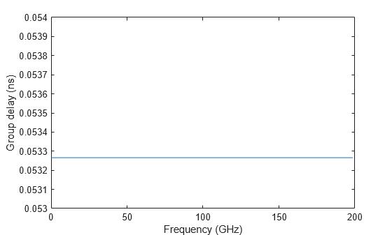
    Use the groupdelay function to compute the group delay of the transmission line. Compute the group delay of the transmission line.

    gd_ns = groupdelay(coaxLine,freq,"Impedance",Z0)*1e9;

    Plot the group delay.

    plot(freq/1e9, gd_ns)
    ylim([floor(min(gd_ns*1e3)) ceil(max(gd_ns*1e3))]./1e3)
    ylabel('Group delay (ns)')
    xlabel('Frequency (GHz)')

    Figure contains an axes object. The axes object with xlabel Frequency (GHz), ylabel Group delay (ns) contains an object of type line.

    Compute S-parameters

    Compute S-parameters of the transmission line for the given frequency sweep and plot S21 phase.

    s = sparameters(coaxLine,freq);
    rfplot(s,2,1,"angle")

    Figure contains an axes object. The axes object with xlabel Frequency (GHz), ylabel Angle (degrees) contains an object of type line. This object represents angle(S_{21}).

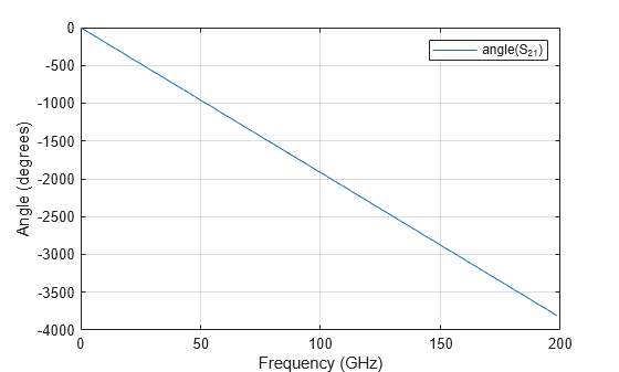
    Therefore, we have enough frequency resolution to ensure that the unwrapped phase S21 is decreasing with frequency.

    Compute TDR

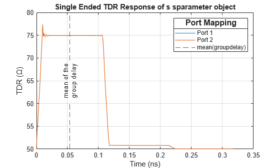
    Use tdr function to plot the TDR.

    plot(tdr(s,EndTime=(6*travel_time)))

    Overlay the mean value of the group delay on the TDR plot.

    hold on
    xline(mean(gd_ns), '--', {'mean of the','group delay'}, ...
        'DisplayName','mean(groupdelay)',...
        'LabelVerticalAlignment','middle',...
        'LabelHorizontalAlignment','center');

    Figure contains an axes object. The axes object with title Single Ended TDR Response of s sparameter object, xlabel Time (ns), ylabel TDR (\Omega) contains 3 objects of type line, constantline. These objects represent Port 1, Port 2, mean(groupdelay).

    Conclusion

    The TDR delay is the time it takes for a signal to enter the input port of the device under test, propagate to the location of a discontinuity, reflect from that discontinuity and then propagate back to the input port. In this case, the discontinuity is the change from the 75 Ω impedance of the DUT to the 50 Ω impedance of the TDR measurement equipment.

    Observe that the TDR delay is equivalent to twice the group delay. This observation is generally true for an uniform transmission line, such as a coaxial transmission line, where the:

    • RLGC is uniformly distributed across the line,

    • dielectric material is lossless, and

    • dielectric material has no frequency dependent dispersion.

    Therefore, in this study, both TDR delay and group delay represent the time it takes for a signal to traverse the structure, provided the line is uniform and is operating below the multimode threshold.

    Version History

    Introduced in R2025a