Model Configuration Simulink Coder Support Package for STMicroelectronics Nucleo Boards
Hardware Implementation Pane Overview

In the Simulink® Editor, select Simulation > Model Configuration Parameters.
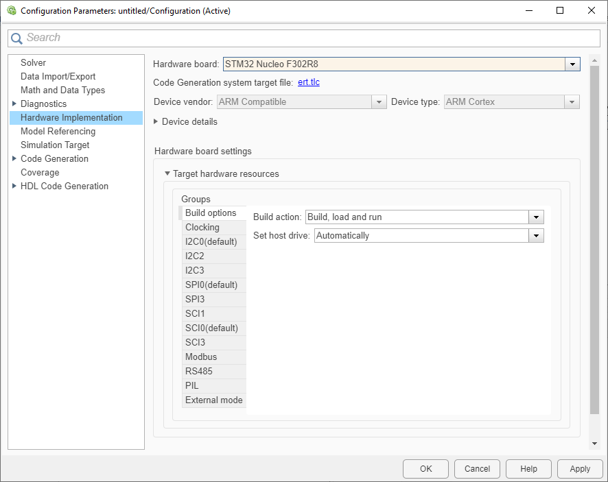
In the Configuration Parameter dialog box, click Hardware Implementation.
Set the Hardware board parameter to one of the Nucleo boards, for eg.
STM32 Nucleo F302R8.The parameter values under Hardware board settings are automatically populated to their default values.
You can optionally adjust these parameters for your particular use case.
Click Apply to apply the changes.
Note
In the Configuration Parameter dialog box, go to Code Generation > Interface > Code interface and ensure Code interface packaging is
set to Nonreusable function.
For more information on selecting a hardware support package and general configuration settings, see Hardware Implementation Pane.
Build options
| Parameter | Description |
|---|---|
Defines how Embedded Coder® responds when you build your model. | |
| The option to copy the generated output bin file automatically or manually to a drive. | |
| The drive on which to copy the generated output bin file manually. |
Clocking
| Parameter | Description |
|---|---|
The CPU clock frequency in MHz. |
Ethernet
Ethernet
| Parameter | Description | Default Value |
|---|---|---|
Select this parameter to configure the board to get an IP address from the local DHCP server on the network. |
| |
Provides the name of the hardware board selected. |
| |
Select this parameter to set the IP address of the board. |
| |
Specify the subnet mask for the board. |
| |
Set the serial gateway to the gateway required to access the target computer. |
| |
Specify the media access control (MAC) address, the physical network address of the board. |
|
I2C
| Parameter | Description |
|---|---|
| Defines the rate of data communication between the peripherals connected by the I2C bus. | |
| Serial clock (SCL) pin | Sets serial clock (SCL) pin. |
| Serial data (SDA) pin | Sets serial data (SDA) pin. |
SPI
| Parameter | Description |
|---|---|
| Serial data out (SDO) pin | The pin that connects the master output to the slave input. |
| Serial data in (SDI) pin | The pin that connects the slave output to the master input. |
| Clock (SCK) pin | The clock pin for SPI communication. |
SCI
| Parameter | Description |
|---|---|
| Baudrate (in Hz) | Defines how fast the data is sent over a serial line. |
| Receive pin | Sets the receiving pin of UART. |
| Transmit pin | Sets the transmitting pin of UART. |
| Data bits length | Sets the number of data bits to transmit. |
| Parity | Sets the type of parity checking to identify low-level errors. |
| Stop bits | Sets the number of stop bits to indicate end of a packet. |
PIL
| Parameter | Description |
|---|---|
| The serial interface used for PIL communication | |
| Serial port | The serial port for PIL communication |
External mode
Build Options
| Parameter | Description |
|---|---|
| Communication interface | The option is used for running your model in External mode with serial communication |
| Serial port | The serial port used by the target hardware |
| Verbose | The option to view the External mode execution progress and the updates in Diagnostic Viewer or MATLAB Command Window |
| Logging buffer size (in bytes) | Specify the logging buffer size. |
| Use a dedicated timer to improve time stamp accuracy | Enable the parameter to use a dedicated timer to improve the time stamp accuracy. |
Connected IO
| Parameter | Description |
|---|---|
| Serial port | The serial port used by the target hardware |
CAN#
| Parameter | Description |
|---|---|
| Baudrate in bits/s (1e9/((BS1+BS2+1)*Tq)) | Baudrate in bits/s of the CAN bus. |
| Receive pin | Set the receiving pin of CAN. |
| Transmit pin | Set the transmitting pin of CAN. |
| Test Mode | Set operating mode for CAN interface. |
Modbus
| Parameter | Description | Default Value |
|---|---|---|
| Communication interface | Type of communication interface that the block will use for Modbus® communication | RS485 |
| Mode | Modbus mode of operation | Client |
| Server ID | Server device address or identifier | 1 |
| Configure Coils | Configure coil register parameters | Selected |
| Configure Discrete Inputs | Configure discrete input register parameters | Selected |
| Configure Holding registers | Configure holding register parameters | Selected |
| Configure Input registers | Configure input register parameters | Selected |
| Received timeout (ms) | Maximum time in milliseconds the master waits for a response from Modbus server | 100 |
RS485
| Parameter | Description | Default Value |
|---|---|---|
| Serial Module | Serial module (port) that the block will use for Modbus communication | SCI 0 |
| DE Pin | Data Enable pin number | 8 |
| RE Pin | Receive Enable pin number | 9 |
ThingSpeak
| Parameter | Description | Default Value |
|---|---|---|
| ThingSpeak server connection timeout (in s) | Specify the ThingSpeak server connection timeout in seconds. | 3 |
| ThingSpeak server response timeout during write (in s) | Specify the ThingSpeak server response timeout during write operation in seconds. | 1 |
| ThingSpeak server response timeout during read (in s) | Specify the ThingSpeak server response timeout during read operation in seconds. | 5 |