Generate Code to Manually Deploy ROS 2 Node from Simulink
This example demonstrates how to generate C++ code from a Simulink® model and deploy it as a standalone ROS 2 node. The workflow begins with generating the code on your host machine and manually transferring it to the remote ROS 2 device. Note that no direct hardware connection is required for this transfer. For a fully automated deployment process, refer to Generate Standalone ROS 2 Node from Simulink.
Prerequisites
This example requires Simulink Coder™.
Refer to the ROS Toolbox System Requirements page for more information, if you are deploying a ROS node for the first time.
Set up Docker in your host environment (Windows Subsystem for Linux (WSL), Linux®, or Mac) and create a Docker® image. For detailed configuration steps, refer to Install and Set Up Docker for ROS, ROS 2, and Gazebo.
Review the example Feedback Control of a ROS-Enabled Robot over ROS 2, which explains the Simulink model used for generating code.
Start Docker Container
With the prerequisites set up and the Docker image created, the first step is to launch an instance of Docker container.
To start a Docker container, run the following command in WSL/Linux/Mac terminal:
$ docker run -it --net=host -v /dev/shm:/dev/shm --name ros2_sl_node <image-name>
Here, 'ros2_sl_node' is the name of the Docker container. Replace the <image-name> with the name of the Docker image created in the prerequisite section.
Get IP Address of Docker Container
While the Docker container is running, obtain the IP address of the Docker container running on the remote device. This IP address is necessary for establishing an SSH connection and accessing the Gazebo simulator. Note that the IP address of the Docker container is the same as the IP of the host machine.
To retrieve this IP address, run the following command in the WSL/Linux/Mac terminal:
$ ifconfig
The network connection type can vary depending on how host is connected to the remote device. While this example uses an Ethernet connection (eth0), in many cases, a wireless connection (wlan0) may be applicable.
Start Gazebo Robot Simulator
Once the container is running, start the Gazebo robot simulator inside the Docker container.
Open a terminal within the Docker container by executing the following command in the WSL/Linux/Mac terminal:
$ docker exec -it ros2_sl_node /bin/bash
Here, 'ros2_sl_node' is the name of Docker container.
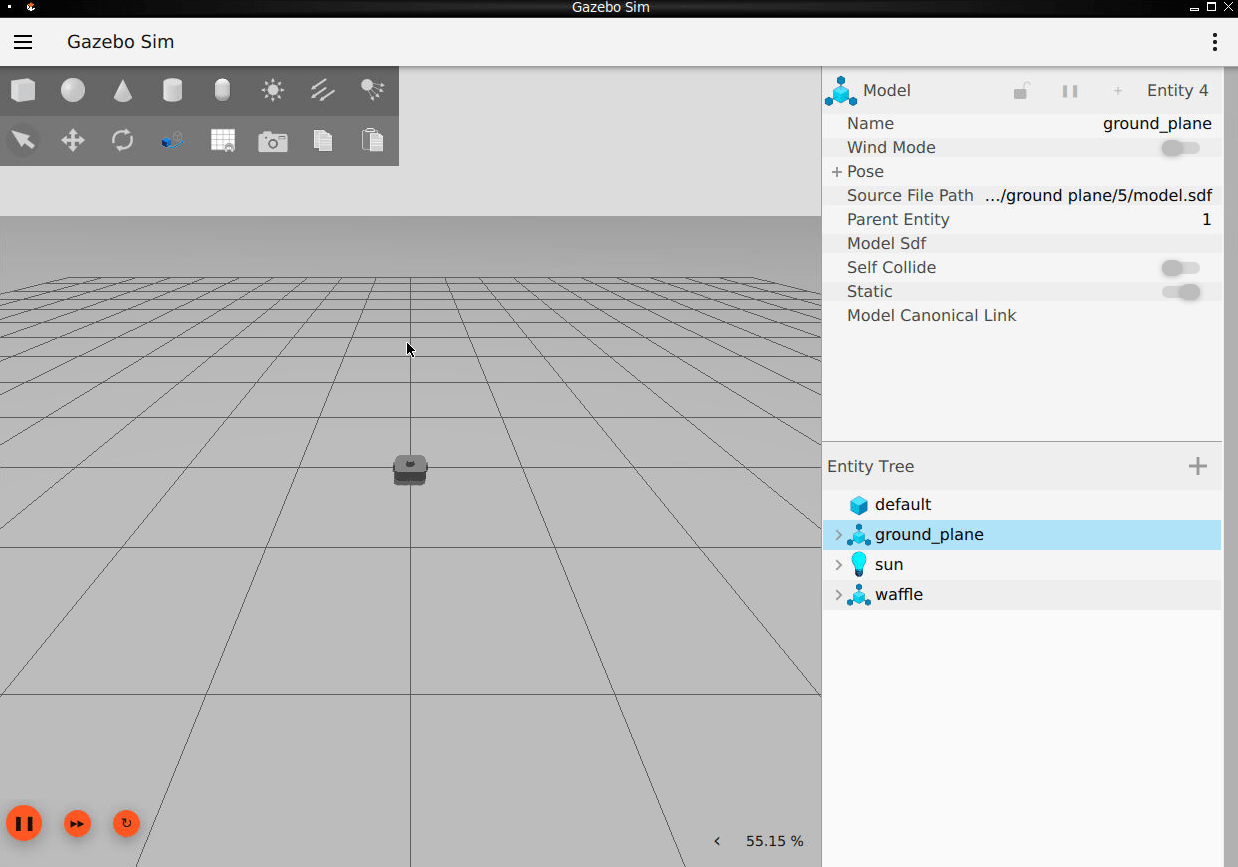
In the Docker container terminal, launch the TurtleBot in a Gazebo world by running the following command:
$ source start-gazebo-empty-world.sh
To view the Gazebo world, open a web browser on your host machine and connect to the URL <docker-ip-address>:8080. If Docker is running on your host machine, you can simply use localhost:8080. You can now visualize and interact with the Gazebo world directly in your web browser.
Configure MATLAB for ROS 2 Network
Launch MATLAB® on your host machine and set the ROS_DOMAIN_ID environment variable to 25 and configure the ROS Middleware in MATLAB to rmw_fastrtps_cpp to match the robot simulator's ROS settings. For detailed steps, refer to Switching Between ROS Middleware Implementations.
Once the domain ID is set, run the following command in MATLAB to verify that the topics from the robot simulator are visible:
setenv('ROS_DOMAIN_ID','25');
ros2 topic list
/camera/camera_info
/camera/image_raw
/camera/image_raw/compressed
/camera/image_raw/compressedDepth
/camera/image_raw/theora
/camera/image_raw/zstd
/clock
/cmd_vel
/imu
/joint_states
/odom
/parameter_events
/robot_description
/rosout
/scan
/tf
/tf_static
The simulator receives and sends messages on the following topics:
Receives
geometry_msgs/Twistvelocity command messages on the/cmd_veltopic.Sends
nav_msgs/Odometrymessages to the/odomtopic.
Configure Model for Code Generation
Configure the model robotFeedbackControllerROS2 to generate C++ code for deploying it as standalone ROS 2 node. This model is a proportional controller introduced in the Feedback Control of a ROS-Enabled Robot over ROS 2 example.
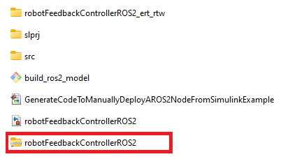
Open the robot feedback control model configured for ROS 2.
open_system("robotFeedbackControllerROS2");Select ROS tab from Simulink toolstrip.
Under ROS tab, click Hardware settings. In the Hardware implementation pane, Hardware board settings section contains settings specific to the generated ROS 2 package, such as information to be included in the
package.xmlfile. Change Maintainer name toROS 2 Example User,clickApply.In the Solver pane, ensure that the solver Type is set to
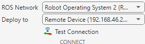
Fixed-step, and set Fixed-step size to0.05, click OK. In generated code, the Fixed-step size defines the actual time step in seconds, that is used for the model update loop (see Execution of Code Generated from a Model (Simulink Coder) (Simulink Coder)). It can be made smaller (e.g., 0.001 or 0.0001) but for current purposes, 0.05 is sufficient.Under ROS tab, from Connect section, set Deploy to Remote Device.
Generate and Deploy ROS 2 Node
Generate the source code for ROS 2 node, then manually deploy and later build it on the Docker container (remote device).
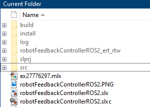
In MATLAB, change the current folder to a location where you have write permission.
Under ROS tab, from the Deploy Type section, select the deployment type as Standard Node.
In ROS tab, from the Deploy section, click Generate Code. If you get any errors about bus type mismatch, close the model, clear all variables from the base MATLAB workspace, and re-open the model. Click the View Diagnostics link at the bottom of the model toolbar to see the output of the code generation process.
Once the code generation completes, a robotFeedbackControllerROS2.tgz which contains the package source code gets written to folder as compressed tgz file.
After generating the tgz file, manually transfer it to the Docker container (remote device). This example assumes you are using the Docker container from Install and Set Up Docker for ROS, ROS 2, and Gazebo. This Docker container is configured to accept SSH connections. If you are using your own Linux system, consult your system administrator for a secure way to transfer files.
To transfer the files through SSH, use ros2device object with following credentials to establish connection with the Docker container:
Username is '
user'Password is '
password'
Run the following command in MATLAB Command Window to create an instance of ros2device and transfer the tgz file to root directory of Docker container:
ipaddress = '<docker_ip_address>';
username = 'user';
password = 'password';
%Create a connection to the ROS 2 device using the specified IP address, username, and password
d = ros2device(ipaddress,username, password);
%Transfer the file 'robotFeedbackControllerROS2.tgz' to the root directory '/home/user' on the ROS 2 device
putFile(d,'robotFeedbackControllerROS2.tgz','/home/user');
Replace <docker_ip_address> with the IP address of your Docker container.
Build ROS 2 Node on Hardware
Once the tgz file is transferred to the home directory of Docker container, unpack the source code and build the ROS 2 node.
Open a Docker terminal, by running the command on WSL/Linux/Mac terminal:
$ docker exec -it ros2_sl_node /bin/bash
On the Docker terminal, execute the following commands to create a ROS 2 workspace and decompress the source code. You may use an existing ROS 2 workspace.
$ mkdir ~/ros2_ws_simulink
$ tar -C ~/ros2_ws_simulink/ -xvf ~/robotFeedbackControllerROS2.tgz
Build the ROS 2 node using the following command in Docker terminal. Replace <path_to_ros2_ws> with the path to your ROS 2 workspace. In this example, the <path_to_ros2_ws> is ~/ros2_ws_simulink. (Note: The build process might display some warnings, such as unused parameters. These parameters are required only for the Simulink environment and do not affect the build process)
$ cd <path_to_ros2_ws>
$ source /opt/ros/jazzy/local_setup.sh
$ colcon build
Verify that the node executable is created using this command below. If the executable is created successfully, this command lists information about the file.
file ~/ros2_ws_simulink/install/robotfeedbackcontrollerros2/lib/robotfeedbackcontrollerros2/robotFeedbackControllerROS2
The model is now ready to be run as a standalone ROS 2 node on your device.
Run ROS 2 Node on Hardware
Once the executable is created, run the ROS 2 node.
On the Docker terminal, execute the following commands to set up the environment variables, then run the ROS 2 node using:
$ export ROS_DOMAIN_ID=25
$ source /opt/ros/jazzy/local_setup.sh
$ ~/<path_to_ros2_ws>/install/robotfeedbackcontrollerros2/lib/robotfeedbackcontrollerros2/robotFeedbackControllerROS2
Replace <path_to_ros2_ws> with the path to your ROS 2 workspace. In this example, the <path_to_ros2_ws> is 'ros2_ws_simulink'.
Note: It is possible that the robot spins at an unexpected location, this is because the pose and world is offset in Gazebo. Close Gazebo world using Ctrl+C on Docker terminal then relaunch Gazebo and the deployed node.
You can also use ros2 node list to list all running nodes in the ROS 2 network. This must display the robotFeedbackControllerROS2 node in the list.
ros2('node','list')
Verify that this ROS 2 node publishes data on the ROS 2 topic, /cmd_vel, to control the motion of simulated robot.
ros2('topic','list')
If you are unable to see the expected node and topic, try to set ROS_DOMAIN_ID using the setenv command in MATLAB Command Window.
setenv("ROS_DOMAIN_ID","25")
Clean Up Docker container
To delete Docker container, run the following command in WSL/Linux/Mac terminal:
$ docker rm ros2_sl_node
Here, 'ros2_sl_node' is the name of Docker container.