rfckt.parallel
Parallel connected network
Description
Use the rfckt.parallel object to create networks of linear
RF objects connected in parallel that are characterized by the components that make up
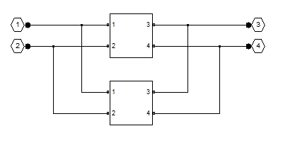
the network. The following figure shows a pair of networks in a parallel
configuration.
Note
circuit
object and add function is recommended over
rfckt.hybrid because the add
function enables you to insert linear and nonlinear elements into a
circuit object to create networks of any topology which
includes a hybrid, an inverse hybrid, a parallel, and a series connected
network. (since R2023b)
Creation
Description
h = rfckt.parallel returns a parallel connected
network object whose properties all have their default values.
h = rfckt.parallel('Ckts',value) returns a cascaded
network with elements specified in the name-value pair property
Ckts.
Properties
Object Functions
analyze | Analyze RFCKT object in frequency domain |
calculate | Calculate specified parameters for rfckt objects or rfdata objects |
circle | Draw circles on Smith Chart |
extract | Extract specified network parameters from rfckt object or data object |
listformat | List valid formats for specified circuit object parameter |
listparam | List valid parameters for specified circuit object |
loglog | Plot specified circuit object parameters using log-log scale |
plot | Plot circuit object parameters on X-Y plane |
plotyy | Plot parameters of RF circuit or RF data on xy-plane with two Y-axes |
getop | Display operating conditions |
polar | Plot specified object parameters on polar coordinates |
semilogx | Plot RF circuit object parameters using log scale for x-axis |
semilogy | Plot RF circuit object parameters using log scale for y-axis |
smith | Plot circuit object parameters on Smith Chart |
write | Write RF data from circuit or data object to file |
getz0 | Calculate characteristic impedance of RFCKT transmission line object |
read | Read RF data from file to new or existing circuit or data object |
restore | Restore data to original frequencies |
getop | Display operating conditions |
groupdelay | Group delay of S-parameter object or RF filter object or RF Toolbox circuit object |
Examples
Algorithms
The analyze method computes the S-parameters of the
AnalyzedResult property using the data stored in the
Ckts property as follows:
The
analyzemethod first calculates the admittance matrix of the parallel connected network. It starts by converting each component network's parameters to an admittance matrix. The following figure shows a parallel connected network consisting of two 2-port networks, each represented by its admittance matrix.
where
The
analyzemethod then calculates the admittance matrix for the parallel network by calculating the sum of the individual admittances. The following equation illustrates the calculations for two 2-port circuits.Finally,
analyzeconverts the admittance matrix of the parallel network to S-parameters at the frequencies specified in theanalyzeinput argumentfreq.
References
[1] Ludwig, R. and P. Bretchko, RF Circuit Design: Theory and Applications, Prentice-Hall, 2000.
Version History
Introduced before R2006a