LBL
Label

Libraries:
Description
The LBL block implements the LBL ladder logic
instruction. This block is used along with JMP block. The rung execution jumps
to the block referenced by LBL block. The LBL should be the
first instruction in the rung.
Examples
This example shows how to model a ladder diagram in Simulink® that uses the JMP and LBL instructions. Simulate the ladder diagram to verify its behavior and generate ladder diagram code from the model. The JMP and LBL instructions branch and loop the ladder diagram code.
Open the Model
The model consists of:
A PLC Controller Suite block named
SequentialMotorControllerthat implements theJMPandLBLinstructions and other logic to control motorsThe blocks in the Human Machine Interface (
HMI), which you can use to interact with the model
Open the model.
mdl = "LadderDiagramJmpAndLblModel";
open_system(mdl);
HMI Section
The HMI section contains blocks that you can use to interact with the model simulation. This image shows the components of the HMI section:
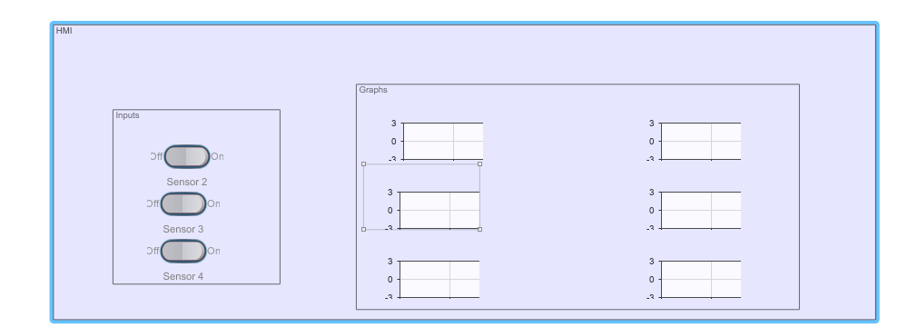
This HMI section contains:
Inputs: You can use the
Sensor 2,Sensor 3, andSensor 4rocker switches to change the value of the respective inputs. When the rocker switch is in theOnposition, the value of the corresponding input is1.Graphs: The Dashboard Scope blocks display the status of
Sensor2,Sensor3,Sensor4,Motor2,Motor3, andMotor4signals, against time as the model simulation progresses.
PLC Controller Suite Block
The PLC Controller Suite block named SequentialMotorController block contains a Program block that houses the ladder logic. To view the ladder logic, open SequentialMotorController, Task block, and then the Program block. This image shows the ladder logic implementation that uses the JMP and LBL instructions for branching and looping.
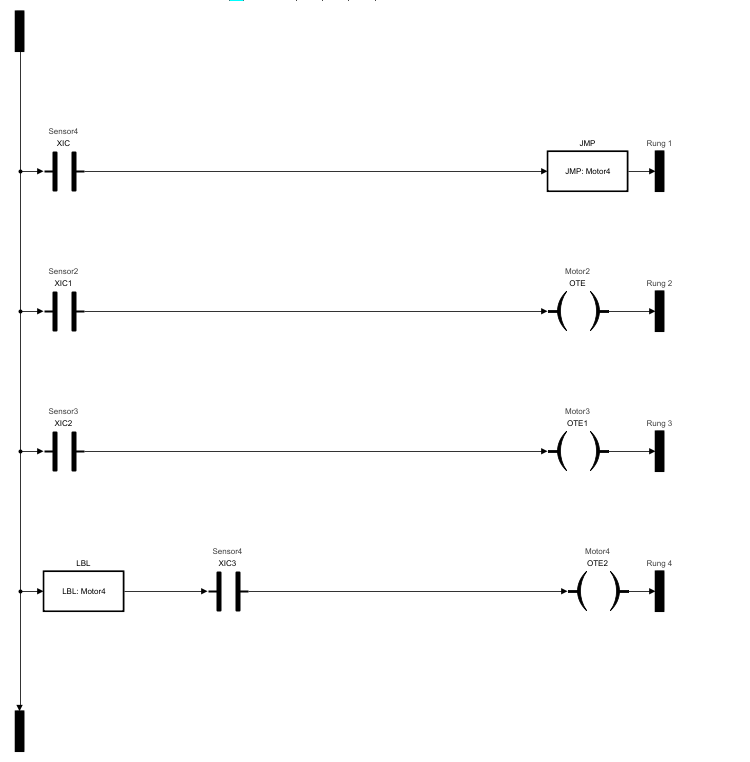
The first rung contains the normally open (XIC) contact and a JMP block that jumps to the label Motor4 when Sensor4 is on. Rungs two and three turn on Motor2 and Motor3 based on the states of Sensor2 and Sensor3. Rung four contains the LBL instruction with the name Motor4.
Simulate and Validate the JMP and LBL Instructions
JMP and LBL instructions are elements in ladder diagrams that control branching and looping in the control logic. The JMP instruction enables conditional branching, which allows the control logic to choose between different paths. The LBL instruction enables looping, which allows the control logic to repeat a set of instructions until a certain condition is met. The JMP and LBL instructions should be used together and the LBL instruction should be the first instruction on a rung. To validate the ladder diagram model:
Ensure that rungs two and three execute normally when the
JMPandLBLinstructions are disabled.The outputs on rungs two and three do not change state when the
JMPandLBLinstructions are enabled.
Before simulating and validating the mode, load the built-in data types, by using the plcloadtypes function.
plcloadtypes
To ensure that rungs two and three execute normally, turn on the Sensor2 and Sensor3 rocker switches in the top model and simulate the model. The Dashboard Scope blocks indicate that Motor2 and Motor3 turn on as soon as Sensor2 and Sensor3 turn on.

To ensure that rungs two and three do not execute when the JMP and LBL instructions are enabled, turn on Sensor4, turn off Sensor2 and Sensor3 and simulate the model. Motor4 turns on and Motor2 and Motor3 stay on. This image shows that after Sensor4 turn on and Sensor2 and Sensor3 turn off, Motor2 and Motor3 stay on.

Generate Code
After validating the operation of the JMP and LBL instructions, generate code for the PLC Controller Suite block. To generate ladder diagram code use the plcgeneratecode function:
generatedFiles = plcgeneratecode("LadderDiagramJmpAndLblModel/SequentialMotorController");
Ports
Input
Output
Parameters
Version History
Introduced in R2019a