Integrated Sensing and Communication II: Communication-Centric Approach Using MIMO-OFDM
This example shows how to model a communication-centric Integrated Sensing and Communication (ISAC) system based on a generic MIMO-OFDM communications system. Part I of this example shows how to model a radar-centric ISAC system based on a MIMO radar transmitting a PMCW waveform.
Introduction
ISAC systems represent a pivotal strategy devised to address challenges posed by the increasingly congested frequency spectrum and the escalating demand for large bandwidth by radar and communicationa systems. In an ISAC framework, both radar and communication functionalities are integrated to share the same hardware infrastructure, utilizing a common transmit waveform. This example shows how radar sensing capabilities can be added to a typical MIMO (Multiple Input Multiple Output) OFDM (Orthogonal Frequency Division Multiplexing) communicationa system.
OFDM is a multicarrier signal composed of a set of orthogonal complex exponentials known as subcarriers. The complex amplitude of each subcarrier can be used to carry communication data allowing for a high data rate. OFDM waveforms were also noted to exhibit Doppler tolerance and a lack of range-Doppler coupling. These OFDM features are attractive to radar applications. Given that the radar functionality is embedded within the communications system, this ISAC method is characterized as communication-centric.
This example considers a bistatic topology aimed at achieving dual objectives. The primary goal of the transmitter is to efficiently deliver a data payload to the receiver across multiple spatial channels. Concurrently, the receiver is tasked with not only receiving this data payload but also with the sensing of the surrounding environment. This is accomplished through the measurement of positions of specific targets of interest.

System Parameters
Consider a MIMO OFDM communications system operating at a carrier frequency of 6 GHz with a bandwidth of 100 MHz.
% Set the random number generator for reproducibility
rng('default');

carrierFrequency = 6e9;                                                 % Carrier frequency (Hz)
waveLength = freq2wavelen(carrierFrequency);                            % Wavelength
bandwidth = 100e6;                                                      % Bandwidth (Hz)
sampleRate = bandwidth;                                                 % Assume the sample rate is equal to the bandwidth
Create a transmitter assuming the peak transmit power is 1 W.
peakPower = 1.0;                                            % Peak power (W)
transmitter = phased.Transmitter('PeakPower', peakPower, 'Gain', 0);
Create a receiver and set the noise figure to 3 dB and the reference noise temperature to 290 K.
noiseFigure = 3.0;                                                      % Noise figure (dB)
referenceTemperature = 290;                                             % Reference temperature (K)
receiver = phased.Receiver('SampleRate', sampleRate, 'NoiseFigure', noiseFigure,...
    'ReferenceTemperature', referenceTemperature, 'AddInputNoise', true,...
    'InputNoiseTemperature', referenceTemperature, 'Gain', 0);
Let both the transmitter and the receiver have a uniform linear array (ULA) of eight isotropic antennas spaced at half a wavelength apart.
Ntx = 8;                                                                % Number of Tx antenna elements
Nrx = 8;                                                                % Number of Rx antenna elements

element = phased.IsotropicAntennaElement('BackBaffled', true);
txArray = phased.ULA(Ntx, waveLength/2, 'Element', element);
rxArray = phased.ULA(Nrx, waveLength/2, 'Element', element);
ISAC Scenario
Let the transmitter be located at the origin. Point the transmit array normal along the x-axis.
txPosition = [0; 0; 0];                                                 % Tx location
txOrientationAxis = eye(3);                                             % Tx array orientation
Let the receiver be some distance away from the transmitter with the receive array normal pointing along the negative y-axis.
rxPosition = [80; 60; 0];                                               % Rx location
rxOrientationAxis = rotz(-90);                                          % Rx array orientation
This example assumes that the transmitter and the receiver are static.
The environment encompassing the area between the transmitter and the receiver is populated with scatterers. These scatterers can be static or they can be moving. A rich scattering environment is a crucial aspect of MIMO communication that allows for spatial multiplexing. Within the context of the sensing function, the scatterers present in the communication channel, regardless of their state of motion, are considered as radar targets.
Assume the maximum path lengths between the transmitter and the receiver is 300 m and the moving scatterers have velocities that do not exceed 50 m/s.
maxPathLength = 300;                                                    % Maximum path lengths between Tx and Rx (m)
maxVelocity = 50;                                                       % Maximum relative velocity (m/s)
Consider a scenario with three moving scatterers. These three scatterers are the targets of interest for the sensing function.
targetPositions = [60 70 90;                                            % Target positions (m)
                   -25 15 30;
                   0 0 0];

targetVelocities = [-15 20 0;                                           % Target velocities (m/s)
                    12 -10 25;
                    0 0 0];

% Platform to model target motion
targetMotion = phased.Platform('InitialPosition', targetPositions, 'Velocity', targetVelocities);

% The values of the reflection coefficients are chosen on random
targetReflectionCoefficients = randn(1, size(targetPositions, 2)) + 1i*randn(1, size(targetPositions, 2));
The rest of the scatterers in the scene are static. Use helperGenerateStaticScatterers helper function to generate positions of the static scatterers within some region of interest.
regionOfInterest = [0 120; -80 80];                                     % Bounds of the region of interest
numScatterers = 200;                                                    % Number of scatterers distributed within the region of interest
[scattererPositions, scattererReflectionCoefficients] = helperGenerateStaticScatterers(numScatterers, regionOfInterest);
Use phased.ScatteringMIMOChannel object to model the propagation channel between the transmitter and the receiver.
channel = phased.ScatteringMIMOChannel('CarrierFrequency', carrierFrequency, 'TransmitArray', txArray,...
    'TransmitArrayPosition', txPosition, 'ReceiveArray', rxArray, 'ReceiveArrayPosition', rxPosition,...
    'TransmitArrayOrientationAxes',txOrientationAxis, 'ReceiveArrayOrientationAxes', rxOrientationAxis,...
    'SampleRate', sampleRate, 'SimulateDirectPath', true, 'ScattererSpecificationSource', 'Input Port');
Visualize the scattering MIMO channel using helperVisualizeScatteringMIMOChannel helper function.
helperVisualizeScatteringMIMOChannel(channel, scattererPositions, targetPositions, targetVelocities)
title('Scattering MIMO Channel for Communication-Centric ISAC Scenario');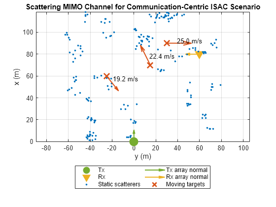
Signaling Scheme
Further, the example shows how to simulate the following signaling scheme for joint communication and sensing:
Initial channel sounding. The transmission starts with a preamble, which is used at the receiver side to obtain the initial channel estimate.
Channel coding. Leveraging the initial channel estimate, the receiver calculates the necessary precoding and combining weights. These precoding weights are then communicated back to the transmitter, under the assumption of perfect feedback without any delays.
Data transmission. The transmitter proceeds to send a single frame divided into two distinct subframes. Subframe A is dedicated to transmitting only the data symbols, whereas subframe B carries both data symbols and pilots, facilitating a dual-purpose transmission that serves both the communication and the sensing function.
Channel estimate and precoding weights update. Upon receiving subframe B, the receiver leverages the pilots to acquire a new channel estimate. This fresh estimate enables the recalibration of both the precoding and combining weights. The updated precoding weights are then relayed back to the transmitter.
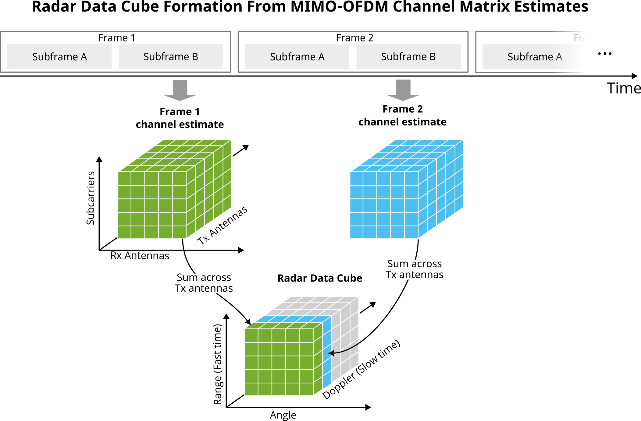
Radar data cube formation. The current channel estimate is summed across the transmit antenna dimension and stored as a separate page in the radar data cube.
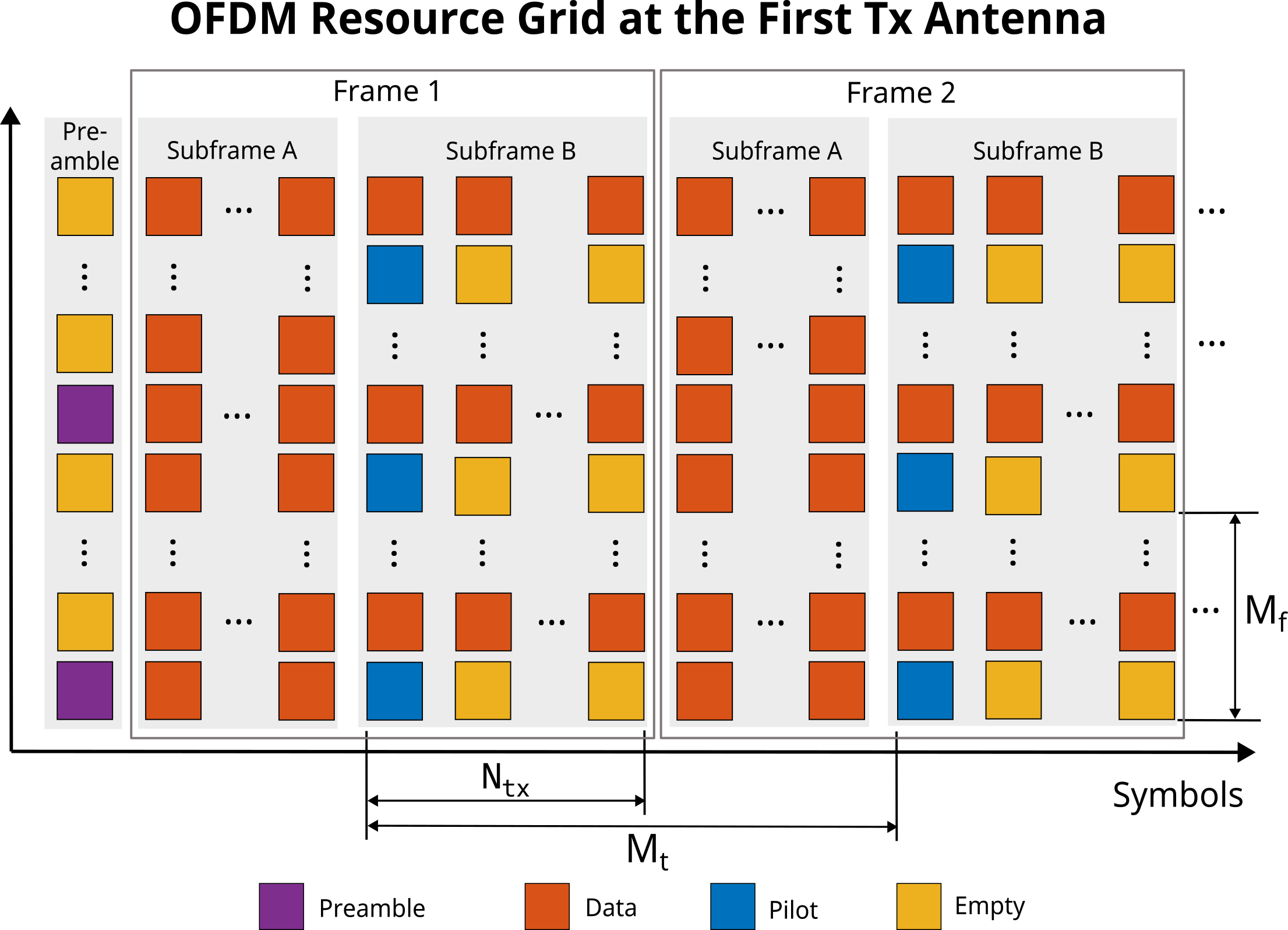
The process continues from step 3 until total numFrames frames are transmitted. After that, target positions and relative velocities can be estimated from the collected radar data cube. The structure of the OFDM resource grid adopted in this example is illustrated below. The diagram illustrates the resource grid at the first transmit antenna. Note the presence of empty resource elements (RE). By allocating preamble and pilots to different subcarriers for different antennas, the system ensures that these critical signals do not interfere with one another.
Let the number of OFDM subcarriers be 2048. Compute the subcarrier separation given that all subcarriers must be equally spaced in frequency.
Nsub = 2048;                                                            % Number of subcarriers
subcarrierSpacing = bandwidth/Nsub;                                     % Separation between OFDM subcarriers
ofdmSymbolDuration = 1/subcarrierSpacing;                               % OFDM symbol duration
To ensure orthogonality of the subcarrier under impact of the Doppler shift due to motion of the scatterers in the channel, the subcarrier spacing must be at least ten times larger than the maximum Doppler shift experienced by the signal. Verify that this condition is met for the scenario considered in this example.
% Maximum Doppler shift based on the maximum relative velocity
maxDopplerShift = speed2dop(maxVelocity, waveLength);
fprintf("Subcarrier spacing is %.2f times larger than the maximum Doppler shift.\n", subcarrierSpacing/maxDopplerShift);
Subcarrier spacing is 48.79 times larger than the maximum Doppler shift.
In order to avoid intersymbol interference, the OFDM symbols are prepended with cyclic prefix. Compute the cyclic prefix duration based on the maximum range of interest.
cyclicPrefixDuration = range2time(maxPathLength);                       % Duration of the cyclic prefix (CP)
cyclicPrefixLength = ceil(sampleRate*cyclicPrefixDuration);             % CP length in samples
cyclicPrefixDuration = cyclicPrefixLength/sampleRate;                   % Adjust duration of the CP to have an integer number of samples
Tofdm = ofdmSymbolDuration + cyclicPrefixDuration;                      % OFDM symbol duration with CP
ofdmSymbolLengthWithCP = Nsub + cyclicPrefixLength;                     % Number of samples in one OFDM symbol
Designate some of the subcarriers as guard bands to avoid spectral leakage from other systems that occupy adjacent frequencies.
% The first 9 and the last 8 subcarriers are used as guard bands
numGuardBandCarriers = [9; 8];

% Total number of subcarriers without guard bands
numActiveSubcarriers = Nsub-numGuardBandCarriers(1)-numGuardBandCarriers(2);
The pilots transmitted in the subframe B are used for both, the channel equalization and radar sensing. Transmitting more pilots both in time and frequency domain results in more data that can be used for the sensing function, however this would reduce the number of REs available to carry the data payload. In [4] it is shown that the maximum spacing between the pilots in time and frequency depends on the maximum expected time delay and the maximum expected Doppler shift. In time the pilots should not be separated by more than
symbols, where is the OFDM symbol duration with cyclic prefix, and is the maximum expected Doppler shift. Similarly, in the frequency domain the pilots should be spaced no more than
subcarriers apart.
Compute maximum possible pilot separation in time and frequency.
Mt = floor(1/(2*maxDopplerShift*Tofdm))
Mt =
22
maxDelay = range2time(maxPathLength)/2;
Mf = floor(1/(2*subcarrierSpacing*maxDelay))
Mf =
10
The pilots used for channel estimation must be transmitted once per frame. Set the length of the OFDM frame to the required pilot spacing in time.
frameLength = Mt;
Each transmit antenna transmits its pilots in a separate OFDM symbol to avoid interference. Therefore, the lengths of the subframe B that carries the pilots is equal to the number of transmit antennas. The rest of the symbols in a frame belong to the subframe A.
subframeALength = frameLength - Ntx;
subframeBLength = Ntx;
A fresh channel matrix estimate is obtained every symbols. The channel matrix has dimensions of Nsub x Ntx x Nrx. The radar data cube can be formed from the series of channel matrix estimates by first summing the channel matrix across the transmit antenna dimension and then stacking them into a Nsub x Nrx x Nframe matrix, where Nframe is the number of recorded frames.
Initial Channel Sounding
The preamble is used to obtain the initial channel estimate and compute the precoding and the combining weights needed to set up spatial multiplexing. In this example the preamble comprises a single OFDM symbol. Different transmit antennas use different subcarriers to transmit the preamble in order to avoid interference (if a subcarrier is occupied by one of the antennas it is a null subcarrier for all other antennas).
For each transmit antenna designate a different subset of subcarriers to carry the preamble symbol.
% Indices of the non-null preamble subcarriers at the first transmit antenna
idxs = [(numGuardBandCarriers(1)+1):Ntx:(Nsub/2-Ntx+1)...
    (Nsub/2+2):Ntx:(Nsub-numGuardBandCarriers(2)-Ntx+1)]';
numPreambleSubcarriers = numel(idxs);

% Shift subcarrier indices by one at each subsequent transmit antenna
preambleIdxs = zeros(numPreambleSubcarriers, 1, Ntx);
for i = 1:Ntx
    preambleIdxs(:, 1, i) = idxs + 1*(i-1);
end
Preamble must contain known values. Uses values generated from a maximum length sequence (MLS) as a preamble.
% Use a known sequence as a preamble. The same values are transmitted by all of
% the transmit antennas.
preamble = mlseq(Nsub - 1);
preamble = preamble(1 : numPreambleSubcarriers);
preamble = repmat(preamble, 1, 1, Ntx);
Create a comm.OFDMModulator object to generate the transmit OFDM preamble symbol and a comm.OFDMDemodulator object to process the received OFDM preamble symbol.
preambleMod = comm.OFDMModulator("CyclicPrefixLength", cyclicPrefixLength,...
    "FFTLength", Nsub, "NumGuardBandCarriers", numGuardBandCarriers,...
    "NumSymbols", 1, "NumTransmitAntennas", Ntx,...
    "PilotCarrierIndices", preambleIdxs, "PilotInputPort", true);
preambleInfo = info(preambleMod);

preambleDemod = comm.OFDMDemodulator(preambleMod);
preambleDemod.NumReceiveAntennas = Nrx;
Transmit the generated preamble OFDM symbol through the channel, add thermal noise at the receiver, and perform demodulation.
% When channel sounding is performed, almost all sub carries are used for
% the preamble. Null the remaining subcarriers.
preambleSignal = preambleMod(zeros(preambleInfo.DataInputSize), preamble);

% Transmit signal
txSignal = transmitter(preambleSignal);

% Apply scattering MIMO channel propagation effects
channelSignal = channel(txSignal, [scattererPositions targetPositions],...
    [zeros(size(scattererPositions)) targetVelocities],...
    [scattererReflectionCoefficients targetReflectionCoefficients]);

% Add thermal noise at the receiver
rxSignal = receiver(channelSignal);

% Demodulate the received signal
[~, rxPreamblePilots] = preambleDemod(rxSignal);
Use helperInterpolateChannelMatrix helper function to compute the channel estimate and the diagbfweights function to compute the precoding and the combining weights.
% Estimate channel matrix
channelMatrix = helperInterpolateChannelMatrix(Nsub, numGuardBandCarriers, squeeze(preamble), squeeze(rxPreamblePilots), preambleIdxs);

% Compute precoding and combining weights
[Wp, Wc, ~, G] = diagbfweights(channelMatrix);
Data Frame Transmission
Create comm.OFDMModulator and comm.OFDMDemodulator objects for modulating and demodulating signals in the subframe A.
% Subframe A contains only data
subframeAMod = comm.OFDMModulator("CyclicPrefixLength", cyclicPrefixLength,...
    "FFTLength", Nsub, "NumGuardBandCarriers", numGuardBandCarriers,...
    "NumTransmitAntennas", Ntx, "NumSymbols", subframeALength);
subframeAInfo = info(subframeAMod);

subframeADemod = comm.OFDMDemodulator(subframeAMod);
subframeADemod.NumReceiveAntennas = Nrx;
The pilots are spaced subcarriers apart in frequency. At each transmit antenna the pilots occupy the same subcarriers. To avoid interference each antenna transmits its pilots in a separate OFDM symbol. Use MLS sequences to generate pilots for all transmit antennas.
pilotIdxs = [(numGuardBandCarriers(1)+1):Mf:(Nsub/2) (Nsub/2+2):Mf:(Nsub-numGuardBandCarriers(2))]';
pilots = zeros(numel(pilotIdxs), Ntx, Ntx);
for itx = 1:Ntx
    s = mlseq(Nsub-1, itx);
    pilots(:, itx, itx) = s(1:numel(pilotIdxs));
end
Create comm.OFDMModulator and comm.OFDMDemodulator objects for modulating and demodulating OFDM signals in the subframe B.
subframeBMod = comm.OFDMModulator("CyclicPrefixLength", cyclicPrefixLength,...
    "FFTLength", Nsub, "NumGuardBandCarriers", numGuardBandCarriers,...
    "NumTransmitAntennas", Ntx, "NumSymbols", Ntx,...
    "PilotCarrierIndices", pilotIdxs, "PilotInputPort", true);
subframeBInfo = info(subframeBMod);

subframeBDemod = comm.OFDMDemodulator(subframeBMod);
subframeBDemod.NumReceiveAntennas = Nrx;

% Indices of data subcarriers in the subframe B
subframeBdataSubcarrierIdxs = setdiff(numGuardBandCarriers(1)+1:(Nsub-numGuardBandCarriers(2)), pilotIdxs);
Assume that the radar data collected from the total of twenty four OFDM frames can be processed coherently. The Doppler resolution is inversely proportional to the coherent observation time know as coherent processing interval (CPI). Compute the velocity resolution that can be achieved with sixteen frames.
Nframe = 24;                                                            % Total number of transmitted OFDM frames
fprintf("Velocity resolution: %.2f (m/s).\n", dop2speed(1/(Nframe*Tofdm*Mt), waveLength));
Velocity resolution: 4.21 (m/s).
OFDM can carry modulated signals. With higher order modulation it is possible to transmit more bits per OFDM symbol. Assume the system utilizes 64-QAM.
bitsPerSymbol = 6;                                                      % Bits per QAM symbol (and OFDM data subcarrier)
modOrder = 2^bitsPerSymbol;                                             % Modulation order
Multiple antennas at the transmitter and the receiver and a rich scattering environment allows for spatial multiplexing. Assume the transmitter is sending two independent data streams to the receiver over two spatial channels.
numDataStreams = 2; % Number of data streamsCompute the input data sizes for the OFDM modulator objects for subframes A and B.
% Input data size for subframe A
subframeAInputSize = [subframeAInfo.DataInputSize(1) subframeAInfo.DataInputSize(2) numDataStreams];

% Input data size for subframe B
subframeBInputSize = [subframeBInfo.DataInputSize(1) subframeBInfo.DataInputSize(2) numDataStreams];
Preallocate space for the radar data.
radarDataCube = zeros(numActiveSubcarriers, Nrx, Nframe);
Simulate formation, transmission, and reception of an OFDM frame one at a time.
for i = 1:Nframe
    % Generate binary payload for subframe A and modulate data using QAM
    subframeABin = randi([0,1], [subframeAInputSize(1) * bitsPerSymbol subframeAInputSize(2) numDataStreams]);
    subframeAQam = qammod(subframeABin, modOrder, 'InputType', 'bit', 'UnitAveragePower', true);

    % Precode data subcarriers for subframe A
    subframeAQamPre = zeros(size(subframeAQam, 1), subframeALength, Ntx);
    for nsc = 1:numActiveSubcarriers
        subframeAQamPre(nsc, :, :) = squeeze(subframeAQam(nsc, :, :))*squeeze(Wp(nsc, 1:numDataStreams,:));
    end

    % Generate OFDM symbols for subframe A
    subframeA = subframeAMod(subframeAQamPre);

    % Generate binary payload for subframe B and modulate data using QAM
    subframeBBin = randi([0,1], [subframeBInputSize(1) * bitsPerSymbol subframeBInputSize(2) numDataStreams]);
    subframeBQam = qammod(subframeBBin, modOrder, 'InputType', 'bit', 'UnitAveragePower', true);

    % Precode data subcarriers for subframe B
    subframeBQamPre = zeros(size(subframeBQam, 1), Ntx, Ntx);
    for nsc = 1:numel(subframeBdataSubcarrierIdxs)
        idx = subframeBdataSubcarrierIdxs(nsc) - numGuardBandCarriers(1);
        subframeBQamPre(nsc, :, :) = squeeze(subframeBQam(nsc, :, :))*squeeze(Wp(idx, 1:numDataStreams,:));
    end

    % Generate OFDM symbols for subframe B
    subframeB = subframeBMod(subframeBQamPre, pilots);

    % Binary data transmitted in the ith frame
    txDataBin = cat(1, subframeABin(:), subframeBBin(:));

    % Reshape and combine subframes A and B to transmit the whole frame
    % one symbol at a time
    subframeA = reshape(subframeA, ofdmSymbolLengthWithCP, subframeALength, []);
    subframeB = reshape(subframeB, ofdmSymbolLengthWithCP, Ntx, []);
    ofdmSignal = [subframeA subframeB];

    % Preallocate space for the received signal
    rxSignal = zeros(size(ofdmSignal, 1), size(ofdmSignal, 2), Nrx);

    % Transmit one OFDM symbol at a time
    for s = 1:size(ofdmSignal, 2)
        % Update target positions
        [targetPositions, targetVelocities] = targetMotion(Tofdm);

        % Transmit signal
        txSignal = transmitter(squeeze(ofdmSignal(:, s, :)));

        % Apply scattering MIMO channel propagation effects
        channelSignal = channel(txSignal, [scattererPositions targetPositions],...
            [zeros(size(scattererPositions)) targetVelocities],...
            [scattererReflectionCoefficients targetReflectionCoefficients]);

        % Add thermal noise at the receiver
        rxSignal(:, s, :) = receiver(channelSignal);
    end

    % Separate the received signal into subframes A and B
    rxSubframeA = rxSignal(:, 1:subframeALength, :);
    rxSubframeA = reshape(rxSubframeA, [], Nrx);

    rxSubframeB = rxSignal(:, subframeALength+1:end, :);
    rxSubframeB = reshape(rxSubframeB, [], Nrx);

    % Demodulate subframe A and apply the combining weights
    rxSubframeAQam = subframeADemod(rxSubframeA);
    rxSubframeAQamComb = zeros(size(rxSubframeAQam, 1), size(rxSubframeAQam, 2), numDataStreams);

    for nsc = 1:numActiveSubcarriers
        rxSubframeAQamComb(nsc, :, :) = ((squeeze(rxSubframeAQam(nsc, :, :))*squeeze(Wc(nsc, :, 1:numDataStreams))))./sqrt(G(nsc,1:numDataStreams));
    end

    % Demodulate subframe B and apply the combining weights
    [rxSubframeBQam, rxPilots] = subframeBDemod(rxSubframeB);
    rxSubframeBQamComb = zeros(size(rxSubframeBQam, 1), size(rxSubframeBQam, 2), numDataStreams);

    for nsc = 1:numel(subframeBdataSubcarrierIdxs)
        idx = subframeBdataSubcarrierIdxs(nsc) - numGuardBandCarriers(1);
        rxSubframeBQamComb(nsc, :, :) = ((squeeze(rxSubframeBQam(nsc, :, :))*squeeze(Wc(idx, :, 1:numDataStreams))))./sqrt(G(idx, 1:numDataStreams));
    end

    % Demodulate the QAM data and compute the bit error rate for the ith
    % frame
    rxDataQam = cat(1, rxSubframeAQamComb(:), rxSubframeBQamComb(:));
    rxDataBin = qamdemod(rxDataQam, modOrder, 'OutputType', 'bit', 'UnitAveragePower', true);
    [~, ratio] = biterr(txDataBin, rxDataBin);
    fprintf("Frame %d bit error rate: %.4f\n", i, ratio);

    % Estimate channel matrix using pilots in the subframe B
    channelMatrix = helperInterpolateChannelMatrix(Nsub, numGuardBandCarriers, pilots, rxPilots, pilotIdxs);

    % Compute precoding and combining weights for the next frame
    [Wp, Wc, ~, G] = diagbfweights(channelMatrix);

    % Store the radar data
    radarDataCube(:, :, i) = squeeze(sum(channelMatrix, 2));
end
Frame 1 bit error rate: 0.0055
Frame 2 bit error rate: 0.0091
Frame 3 bit error rate: 0.0100
Frame 4 bit error rate: 0.0126
Frame 5 bit error rate: 0.0099
Frame 6 bit error rate: 0.0098
Frame 7 bit error rate: 0.0089
Frame 8 bit error rate: 0.0108
Frame 9 bit error rate: 0.0121
Frame 10 bit error rate: 0.0091
Frame 11 bit error rate: 0.0095
Frame 12 bit error rate: 0.0114
Frame 13 bit error rate: 0.0099
Frame 14 bit error rate: 0.0112
Frame 15 bit error rate: 0.0085
Frame 16 bit error rate: 0.0110
Frame 17 bit error rate: 0.0115
Frame 18 bit error rate: 0.0098
Frame 19 bit error rate: 0.0086
Frame 20 bit error rate: 0.0105
Frame 21 bit error rate: 0.0096
Frame 22 bit error rate: 0.0132
Frame 23 bit error rate: 0.0096
Frame 24 bit error rate: 0.0102
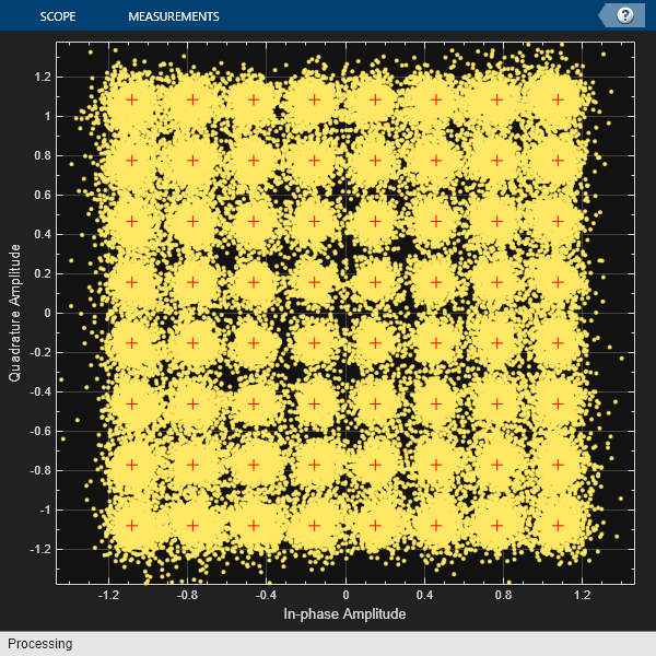
Plot the 64-QAM constellation for the last received OFDM frame.
refconst = qammod(0:modOrder-1, modOrder, 'UnitAveragePower', true);
constellationDiagram = comm.ConstellationDiagram('NumInputPorts', 1, ...
    'ReferenceConstellation', refconst, 'ChannelNames', {'Received QAM Symbols'});

constellationDiagram(rxDataQam);
Radar Data Processing
Assuming the positions of the transmitter and the receiver are known, the collected radar data cube can be processed to estimate positions of the scatterers in the channel. However, the total number of scatterers is very large and not all of them are the targets of interest. If the targets of interest are the moving scatterers, the static scatterers can be filtered out in the Doppler domain since the Doppler shift from a static scatterer is equal to zero.
% Perform FFT over the slow-time dimension and zero out the DC component to
% remove static scatterers
Y = fft(radarDataCube, [], 3);
Y(:, :, 1) = 0;
y = ifft(Y, Nframe, 3);
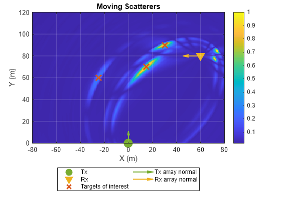
Plot a heatmap indicating the positions of the moving scatterers within the region of interest using helperPositionHeatmap helper class.
% Plot position heat map
phm = helperPositionHeatmap('ReceiveArray', rxArray, 'ReceiveArrayOrientationAxis', rxOrientationAxis, 'ReceiveArrayPosition', rxPosition, ...
    'SampleRate', sampleRate, 'CarrierFrequency', carrierFrequency, 'Bandwidth', bandwidth, 'OFDMSymbolDuration', ofdmSymbolDuration, ...
    'TransmitArrayOrientationAxis', txOrientationAxis, 'TransmitArrayPosition', txPosition, 'TargetPositions', targetPositions, 'ROI', [0 120; -80 80]);

figure;
phm.plot(y)
title('Moving Scatterers')
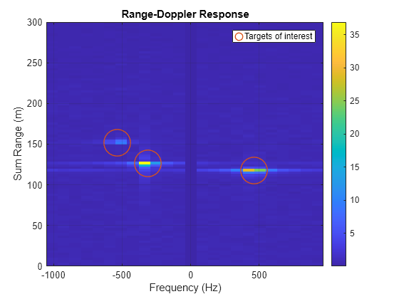
Plot range-Doppler response. Note, the range shown in the range-Doppler response is the sum range and the Doppler shift is the bistatic Doppler shift. To estimate actual target velocity multiple distributed transmitters or receiver are required to form a multi-static radar.
rangeDopplerResponse = phased.RangeDopplerResponse('RangeMethod', 'FFT', ...
    'SampleRate', sampleRate, 'SweepSlope', bandwidth/ofdmSymbolDuration,...
    'PRFSource', 'Property', 'PRF', 1/(Tofdm*frameLength), 'ReferenceRangeCentered', false);

[rdr, r, doppler] = rangeDopplerResponse(conj(y));
doppler = doppler * (-1);   % -1 to account for conj in the range-do response

% Combine signals from all receive antennas using non-coherent integration
rdr_integ = squeeze(sum(abs(rdr), 2));

figure;
imagesc(doppler, r*2, rdr_integ);
ax = gca;
set(ax, 'YDir', 'normal') ;

colorbar;
xlabel('Frequency (Hz)');
ylabel('Sum Range (m)');
title('Range-Doppler Response');
grid on;
ylim([0 maxPathLength]);
hold on;

% Bistatic Doppler
bistaticDoppler = helperBistaticDopplerShift(txPosition, rxPosition, targetPositions, targetVelocities, carrierFrequency);

% Sum range
sumRange = vecnorm(targetPositions - rxPosition) + vecnorm(targetPositions - txPosition);

plot(bistaticDoppler, sumRange, 'o', 'LineWidth', 1, 'MarkerSize', 28, 'Color', '#D95319',...
    'MarkerFaceColor', 'none', 'DisplayName', 'Targets of interest')
legend
Conclusion
This example shows how to integrate radar sensing capabilities within a generic MIMO-OFDM communications system, thereby transforming it into an ISAC system. The example begins by setting up a MIMO-OFDM communications system with a single transmit and a single receive array. It then configures a scattering channel populated with both static and moving scatterers. The system's communication function focuses on data payload delivery, while the primary goal of the sensing function is to detect and estimate positions of the moving scatterers within the channel. Since the radar processing happens at the receiver, the radar configuration considered in this example is bistatic. The example shows how the pilots, which are typically used for channel estimation, can be employed for radar sensing. These pilots are strategically allocated within an OFDM frame to accommodate the maximum expected time delay and target velocity. The example then transmits multiple OFDM frames to acquire consecutive channel matrix estimates and compiles these estimates into a radar data cube. Finally, it shows how positions and bistatic Doppler shifts of the moving scatterers can be estimated from the formed radar data cube.
References
Liu, Fan, Christos Masouros, Athina P. Petropulu, Hugh Griffiths, and Lajos Hanzo. "Joint radar and communication design: Applications, state-of-the-art, and the road ahead." IEEE Transactions on Communications 68, no. 6 (2020): 3834-3862.
Liu, An, Zhe Huang, Min Li, Yubo Wan, Wenrui Li, Tony Xiao Han, Chenchen Liu et al. "A survey on fundamental limits of integrated sensing and communication." IEEE Communications Surveys & Tutorials 24, no. 2 (2022): 994-1034.
de Oliveira, Lucas Giroto, Benjamin Nuss, Mohamad Basim Alabd, Axel Diewald, Mario Pauli, and Thomas Zwick. "Joint radar-communication systems: Modulation schemes and system design." IEEE Transactions on Microwave Theory and Techniques 70, no. 3 (2021): 1521-1551.
Sit, Yoke Leen, Benjamin Nuss, and Thomas Zwick. "On mutual interference cancellation in a MIMO OFDM multiuser radar-communication network." IEEE Transactions on Vehicular Technology 67, no. 4 (2017): 3339-3348.
Supporting Functions
function fd = helperBistaticDopplerShift(txPos, rxPos, tgtPos, tgtVel, fc)
% Doppler shift induced by a target located at tgtPos and moving with a
% velocity tgtVel on a signal transmitted by a static transmitter located
% at txPos and received by a static receiver located at rxPos

txPhi = atan2(txPos(2)-tgtPos(2, :), txPos(1) - tgtPos(1, :));
rxPhi = atan2(rxPos(2)-tgtPos(2, :), rxPos(1) - tgtPos(1, :));

c = physconst("LightSpeed");
fd = -fc * (tgtVel(1, :) .* (cos(txPhi) + cos(rxPhi)) + tgtVel(2, :) .* (sin(txPhi) + sin(rxPhi))) / c;

end