phased.GCCEstimator
Wideband direction of arrival estimation
Description
The phased.GCCEstimator
System object™ creates a direction of arrival estimator for wideband signals. This
System object estimates the direction of arrival or time of arrival among sensor array
elements using the generalized cross-correlation with phase transform algorithm
(GCC-PHAT). The algorithm assumes that all signals propagate from a single source lying
in the array far field so the direction of arrival is the same for all sensors. The
System object first estimates the correlations between all specified sensor pairs using
GCC-PHAT and then finds the largest peak in each correlation. The peak identifies the
delay between the signals arriving at each sensor pair. Finally, a least-squares
estimate is used to derive the direction of arrival from all estimated delays.
To compute the direction of arrival for pairs of element in the array:
Create the
phased.GCCEstimatorobject and set its properties.Call the object with arguments, as if it were a function.
To learn more about how System objects work, see What Are System Objects?
Creation
Description
sGCC = phased.GCCEstimatorsGCC. This object estimates the direction of
arrival or time of arrival between sensor array elements using the GCC-PHAT
algorithm.
sGCC = phased.GCCEstimator(Name=Value)sGCC,
with the specified property Name set to the specified
Value. You can specify several name-value pair arguments
in any order as Name1=Value1,...,NameN=ValueN.
Properties
Usage
Description
ang = sGCC(X)ang, of an input signal
X. The argument X is a matrix
specifying the received signals at the elements of the array specified in the
SensorArray property. Signals propagate from a single
source. Each column in X corresponds to the elements in the
array (if an array is used) or the number of subarrays (if a subarray is used).
Each row of X represents a single time snapshot.
[ returns the estimated
correlations, ang,R,lag]
= sGCC(X)R, between pairs of sensors, when you set the
CorrelationOutputPort property to true.
R is a matrix with P columns where
P is the number of sensor pairs. Each column in
R contains the correlation for the corresponding pair
of sensors. lag is a column vector containing the time lags
corresponding to the rows of the correlation matrix. The time lags are the same
for all sensor pairs.
Note
The object performs an initialization the first time the object is executed. This
initialization locks nontunable properties
and input specifications, such as dimensions, complexity, and data type of the input data.
If you change a nontunable property or an input specification, the System object issues an error. To change nontunable properties or inputs, you must first
call the release method to unlock the object.
Input Arguments
Output Arguments
Object Functions
To use an object function, specify the
System object as the first input argument. For
example, to release system resources of a System object named obj, use
this syntax:
release(obj)
Examples
Estimate the direction of arrival of a signal using the GCC-PHAT algorithm. The receiving array is a 5-by-5-element URA microphone array with elements spaced 0.25 meters apart. The arriving signal is a sequence of wideband chirps. The signal arrives from 17° azimuth and 0° elevation. Assume the speed of sound in air is 340 m/s.
Load the chirp signal.
load chirp;
c = 340.0;
Create the 5-by-5 microphone URA.
d = 0.25;
N = 5;
mic = phased.OmnidirectionalMicrophoneElement;
array = phased.URA([N,N],[d,d],Element=mic);
Simulate the incoming signal using the WidebandCollector System object™.
arrivalAng = [17;0];
collector = phased.WidebandCollector(Sensor=array,PropagationSpeed=c, ...
    SampleRate=Fs,ModulatedInput=false);
signal = collector(y,arrivalAng);
Estimate the direction of arrival.
estimator = phased.GCCEstimator(SensorArray=array, ...
    PropagationSpeed=c,SampleRate=Fs);
ang = estimator(signal)
ang = 2×1
16.4538
-0.7145
Estimate the direction of arrival of a signal using GCC-PHAT. The receiving array is a 5-by-5-element URA microphone array with elements spaced 25 cm apart. Choose 10 element pairs to compute the arrival angle. Assume the speed of sound in air is 340 m/sec. The arriving signal is a sequence of wideband sounds. Assume the signal arrives from azimuth and elevation. Estimate the arrival angle, and then plot the correlation function versus lag for one pair of elements.
Load the signal and extract a small portion (5000 samples) for computation.
load gong
y1 = y(1:5000);
Set up the receiving array.
N = 5;
d = 0.25;
mic = phased.OmnidirectionalMicrophoneElement;
array = phased.URA([N,N],[d,d],Element=mic);
Simulate the arriving plane wave using the WidebandCollector System object™.
c = 340.0;
arrivalAng = [54;5];
coll = phased.WidebandCollector(Sensor=array, ...
    PropagationSpeed=c, ...
    SampleRate=Fs, ...
    ModulatedInput=false);
signal = coll(y1,arrivalAng);
Estimate direction of arrival. Choose 10 sensors to correlate with the first element of the URA.
sensorpairs = [[2,4,6,8,10,12,14,16,18,20];ones(1,10)];
estimator = phased.GCCEstimator(SensorArray=array, ...
    PropagationSpeed=c,SampleRate=Fs, ...
    SensorPairSource="Property", ...
    SensorPair=sensorpairs, ...
    DelayOutputPort=true,CorrelationOutputPort=true);
[estimatedAng,taus,R,lags] = estimator(signal);
The estimated angle is:
disp(estimatedAng)
   53.7028
    4.9552
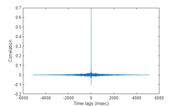
Plot the correlation between sensor 8 and sensor 1. This pair corresponds to the fourth column of the correlation matrix. The estimated value of tau (in msec ) for this pair is:
disp(1000*taus(4))
-0.4757
plot(1000*lags,real(R(:,4)))
xlabel("Time lags (msec)")
ylabel("Correlation")
Algorithms
References
[1] Knapp, C. H. and G.C. Carter, “The Generalized Correlation Method for Estimation of Time Delay.” IEEE Transactions on Acoustics, Speech and Signal Processing. Vol. ASSP-24, No. 4, Aug 1976.
[2] G. C. Carter, “Coherence and Time Delay Estimation.” Proceedings of the IEEE. Vol. 75, No. 2, Feb 1987.
Extended Capabilities
Version History
Introduced in R2015b
See Also
phased.BeamscanEstimator | phased.RootMUSICEstimator | gccphat