Main Content

phased.GaussianAntennaElement

Gaussian antenna element

Since R2021b

Description

The GaussianAntennaElement System object™ models an antenna with a Gaussian Response. Despite being an idealized antenna pattern, the Gaussian is often used to approximate other antennas in simulations because its response closely follows the pattern of many antennas out to about the –10 dB level. The Gaussian beam has no sidelobes. The 0° azimuth and 0° elevation is considered to be the main response axis of the antenna. When placed in a linear or a rectangular array, the main response axis is aligned with the array normal.

To compute the response of the antenna element for specified directions:

  1. Create the phased.GaussianAntennaElement object and set its properties.

  2. Call the object with arguments, as if it were a function.

To learn more about how System objects work, see What Are System Objects?

Creation

Description

antenna = phased.GaussianAntennaElement creates a Gaussian antenna System object, antenna. This object models a Gaussian beam, which closely follows the pattern of many antennas out to about the –10 dB level. The Gaussian beam has no sidelobes.

example

antenna = phased.GaussianAntennaElement(Name=Value) creates a Gaussian antenna object, antenna, with each specified property set to the specified value. You can specify multiple name-value arguments in any order. For example, FrequencyRange=[1e6 1e9] specifies that the antenna operates in a frequency range from 1 MHz to 1 GHz.

Properties

expand all

Unless otherwise indicated, properties are nontunable, which means you cannot change their values after calling the object. Objects lock when you call them, and the release function unlocks them.

If a property is tunable, you can change its value at any time.

For more information on changing property values, see System Design in MATLAB Using System Objects.

Operating frequency range of the antenna, specified as a nonnegative, real-valued, 1-by-2 row vector in the form [LowerBound HigherBound]. The antenna element has no response outside the specified frequency range. Units are in Hz.

Data Types: double

Beamwidth of the antenna pattern, specified as either a scalar or a 1-by-2 real-valued vector. When the specified value is a 1-by-2 vector, it has the form of [AzimuthBeamwidth ElevationBeamwidth]. If the specified value is a scalar, the azimuth and elevation beamwidths are equal. Units are in degrees.

Example: 15

Data Types: double

Usage

Description

example

RESP = antenna(FREQ,ANG) returns the antenna voltage response RESP at operating frequencies specified in FREQ and directions specified in ANG.

Input Arguments

expand all

Operating frequency of the antenna element, specified as a nonnegative scalar or nonnegative, real-valued 1-by-L row vector. Frequency units are in Hz.

FREQ must lie within the range of values specified by the FrequencyRange or the FrequencyVector property of the element. Otherwise, the element produces no response and the response is returned as –Inf. Element objects use the FrequencyRange property, except for phased.CustomAntennaElement, which uses the FrequencyVector property.

Example: [1e8 2e6]

Data Types: double

Azimuth and elevation angles of the response directions, specified as a real-valued 1-by-M row vector or a real-valued 2-by-M matrix, where M is the number of angular directions. Angle units are in degrees. The azimuth angle must lie in the range –180° to 180°, inclusive. The elevation angle must lie in the range –90° to 90°, inclusive.

  • If ANG is a 1-by-M vector, each element specifies the azimuth angle of the direction. In this case, the corresponding elevation angle is assumed to be zero.

  • If ANG is a 2-by-M matrix, each column of the matrix specifies the direction in the form [azimuth;elevation].

The azimuth angle is the angle between the x-axis and the projection of the direction vector onto the xy-plane. This angle is positive when measured from the x-axis toward the y-axis. The elevation angle is the angle between the direction vector and xy-plane. This angle is positive when measured toward the z-axis. See the definition of Azimuth and Elevation Angles.

Example: [110 125; 15 10]

Data Types: double

Output Arguments

expand all

Voltage response of the antenna element, returned as a matrix of size M-by-L. In this matrix, M represents the number of angles specified in ANG and L represents the number of frequencies specified in FREQ.

Data Types: double

Object Functions

To use an object function, specify the System object as the first input argument. For example, to release system resources of a System object named obj, use this syntax:

release(obj)

expand all

directivityDirectivity of antenna or transducer element
beamwidthCompute and display beamwidth of sensor element pattern
patternPlot antenna or transducer element directivity and patterns
patternAzimuthPlot antenna or transducer element directivity and pattern versus azimuth
patternElevationPlot antenna or transducer element directivity and pattern versus elevation
isPolarizationCapableAntenna element polarization capability
stepRun System object algorithm
releaseRelease resources and allow changes to System object property values and input characteristics
resetReset internal states of System object

Examples

collapse all

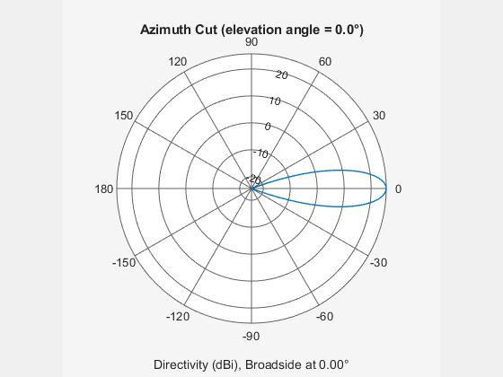
Create a Gaussian antenna and plot its azimuth response. The antenna can work between 800 MHz and 1.2 GHz and has an operating frequency of 1 GHz.

element = phased.GaussianAntennaElement( ...
    FrequencyRange=[800e6 1.2e9]);
fc = 1e9;

pattern(element,fc,-180:180,0,CoordinateSystem="polar")

Find the response of the antenna at the boresight.

ang = [0 0]';
resp = element(fc,ang)
resp = 1

More About

expand all

Extended Capabilities

Version History

Introduced in R2021b