Tilt Angle Estimation Using Inertial Sensor Fusion and ADIS16505
This example shows how to get data from an Analog Devices ADIS16505 IMU sensor and to use a sensor fusion algorithm on the sensor data to compute the tilt of the device.
The ADIS16505 is a 6-axis sensor with accelerometer and gyroscope. The accelerometer measures acceleration and the gyroscope measures angular velocity in x-, y- and z-axis.The following animation shows the tilt angle as the IMU is rotated back and forth:
Required MathWorks Products
MATLAB®
MATLAB Support Package for Arduino® Hardware
Navigation Toolbox™ or Sensor Fusion and Tracking Toolbox™
Required Hardware
Arduino Uno
Analog Devices ADIS16505
Hardware Connection
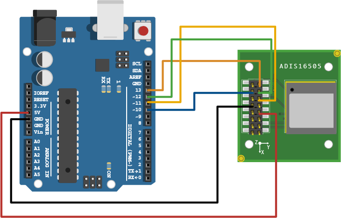
Connect the SLCK, CS, DOUT, DIN, GND, and VDD pins of the ADIS16505 sensor to the corresponding pins on the Arduino Hardware. This example uses the Arduino Uno board with the following connections between ADIS16505 and Arduino Uno:
SCLK - D13
CS - D10
DOUT - D12
DIN - D11
GND - GND
VDD - 5V
Ensure that the connections to the sensors are intact. It is recommended to use a prototype shield and solder the sensor to it to avoid loose connections while moving the sensor. Refer the Troubleshooting Sensors page for sensors to debug the sensor related issues.
Create Sensor Object
Create an arduino object.
a = arduino;
Create the ADIS16505 sensor object. Specify SPI chip select pin as D10 to follow the above hardware connection and the output format as a matrix.
Fs = 100; % Hz
imu = adis16505(a,SampleRate=Fs,SPIChipSelectPin="D10",OutputFormat="matrix");
Aligning the Axis of ADIS16505 Sensor with NED Coordinates
The sensor fusion algorithm used in this example use North-East-Down(NED) as a fixed, parent coordinate system. In the NED reference frame, the x-axis points North, the y-axis points East, and the z-axis points down.
To align ADIS16505 axes to NED coordinates:
1. Define device axes: Define the imaginary axis as the device axis on the sensor in accordance to NED coordinate system which may or may not be same as sensor axes.
2. Swap the x and y values of accelerometer and gyroscope readings, so that the accelerometer and gyroscope axis is aligned with magnetometer axis.
3. Determine polarity values for accelerometer, and gyroscope.
a. Accelerometer
Place the sensor such that device x-axis is pointing downwards, perpendicular to the surface at which sensor is kept. Accelerometer readings should read approximately
[9.8 0.0 0.0]. If not negate the x-values of accelerometer.Place the sensor such that device y-axis is pointing downwards, perpendicular to the surface at which sensor is kept. Accelerometer readings should read approximately
[0.0 9.8 0.0]. If not negate the y-values of accelerometer.Place the sensor such that device z-axis is pointing downwards, perpendicular to the surface at which sensor is kept. Accelerometer readings should read approximately
[0.0 0.0 9.8]. If not negate the z-values of accelerometer.
b. Gyroscope
Rotate the sensor along each axis and capture the readings. Use the right-hand screw rule to correct the polarity of rotation.
The above method is used to set the axis of the sensor in this example.
Accelerometer-Gyroscope Fusion
The imufilter System object™ fuses accelerometer and gyroscope data using an internal error-state Kalman filter. The filter is capable of removing the gyroscope bias noise, which drifts over time. The filter does not process magnetometer data, so it does not correctly estimate the direction of north. The algorithm assumes the initial position of the sensor is in such a way that device x-axis of the sensor is pointing towards magnetic north, the device y-axis of the sensor is pointing to east and the device z-axis of the sensor is pointing downwards. The sensor must be stationary, before the start of this example. The output orientation is processed by the tilt function to obtain the tilt angle of the device.
% GyroscopeNoise and AccelerometerNoise is determined from the datasheet.
GyroscopeNoiseADIS16505 = 3.0462e-06; % GyroscopeNoise (variance) in units of rad/s
AccelerometerNoiseADIS16505 = 0.0061; % AccelerometerNoise (variance) in units of m/s^2
fusionFilt = imufilter(SampleRate=imu.SampleRate,GyroscopeNoise=GyroscopeNoiseADIS16505,AccelerometerNoise=AccelerometerNoiseADIS16505);
stopTimer = 30; % seconds
Initialize figure to visualize tilt angle.
fig = figure;
ax = axes(fig);
initX1 = [-5 0];
initX2 = [0 5];
initY = [0 0];
tiltLine = plot(ax,initX1,initY,"-o",initX2,initY,'-x');
yline(ax,0,Color=ax.ColorOrder(2,:));
set(tiltLine(2),Color=ax.ColorOrder(1,:));
axis(ax,[-10 10 -10 10]);
xticks(ax,[]);
yticks(ax,[]);
tiltMatrix = @(t) [cos(t), -sin(t); sin(t), cos(t)];
While this code is getting executed, slowly move the sensor to see the tilt angle change. Note that the angle will flip when the pitch angle sign changes.
tic;
while(toc < stopTimer)
    [accel,gyro] = read(imu);
    accel = [-accel(:,1), -accel(:,2), accel(:,3)];
    orient = fusionFilt(accel,gyro);
    for ii = numel(orient)
        % Update figure.
        tiltAngle = tilt(orient(ii));
        eulAng = euler(orient(ii),"ZYX","frame");
        pitch = eulAng(2);
        lineData1 = tiltMatrix(sign(pitch).*tiltAngle) * [initX1; initY];
        set(tiltLine(1),XData=lineData1(1,:),YData=lineData1(2,:));
        lineData2 = tiltMatrix(sign(pitch).*tiltAngle) * [initX2; initY];
        set(tiltLine(2),XData=lineData2(1,:),YData=lineData2(2,:));
        title("Pitch: " + num2str(rad2deg(pitch)) + " degrees");
        drawnow limitrate
    end
end

Clean Up
When the connection is no longer needed, release and clear the objects.
release(imu);
clear;