Modeling Baseband PLL and Phase Noise in RF Models
This example shows how to create a complex equivalent baseband signal to accurately represent the output of a PLL design with realistic control loop definition. The signal is used in an RF model created using RF Blockset parts. The example demonstrates the effect of phase noise on a modulated communications signal with or without the use of a baseband PLL from Mixed-Signal Blockset.
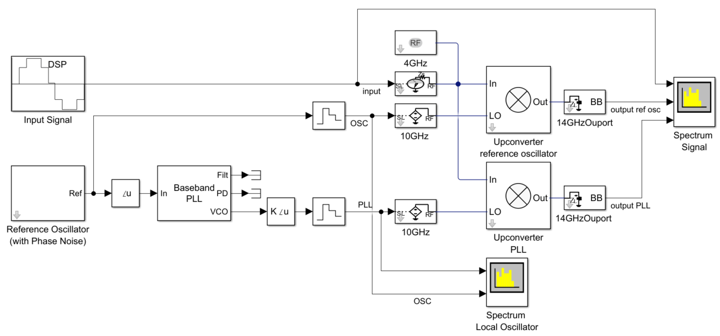
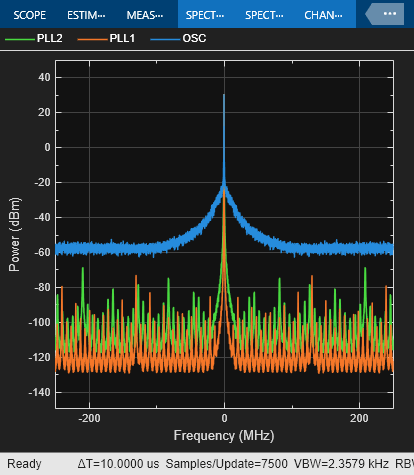
In the model above the 'Reference Oscillator' subsystem creates a signal with a given phase noise profile that is directly used as local oscillator (LO) in an RF upconverter mixer. The same reference signal is then used to drive a PLL with a relatively narrow loop bandwidth. For comparison, the output of the PLL is used to drive a second RF upconverter mixer (i.e. 'Upconverter stage PLL' in the image above). The filtering effects of the PLL on the reference oscillator phase noise are shown in the spectrum scope “Spectrum Local Oscillator”.
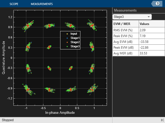
The RF input signal to both mixers is a modulated 16 QAM communications signal. A simple baseband receiver recovers the constellation of the input signal as well as the output of the two mixers. The constellation diagram allows to visualize and compare the three constellations and measure the Error Vector Magnitude (EVM).
After simulating the model we can observe that the input signal has a relatively low EVM (<2%) due to the dynamics of the AGC. The output signal of the mixer that directly uses the reference oscillator as LO has a higher EVM (~6%). The output signal of the mixer that uses the PLL output as LO has a better EVM (~4%) due to the filtering effects of the PLL on the phase noise of the reference oscillator. The effects of lock time are also visible as the simulation progresses.
Baseband PLL Characteristics
The Baseband PLL block from the Mixed-Signal Blockset expects the phase of the reference signal as input. In this example we use a constant (complex) envelope signal with additional phase noise, and extract the angle of the reference signal to be the input of the PLL. The block applies the closed control loop response of a PLL to that signal and outputs a signal that represents the output phase of the PLL. The block also has output ports for signals from the phase detector and loop filter, making it easier to evaluate PLL control loop behaviors such as loop lock time and step response. The reference signal is reconstructed by adding a constant magnitude component, and applied to the RF Blockset's 'Inport'. The signal represents the complex modulation applied to a constant wave (CW) signal in this case set at 3GHz. The 16 QAM communication signal represents the complex modulation centered around the carrier frequency of 1GHz. The circuit envelope solver performs a harmonic balance non-linear analysis using the specified frequencies, and the complex envelope of the upconverted signal.
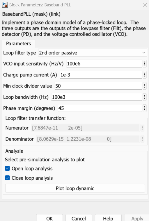
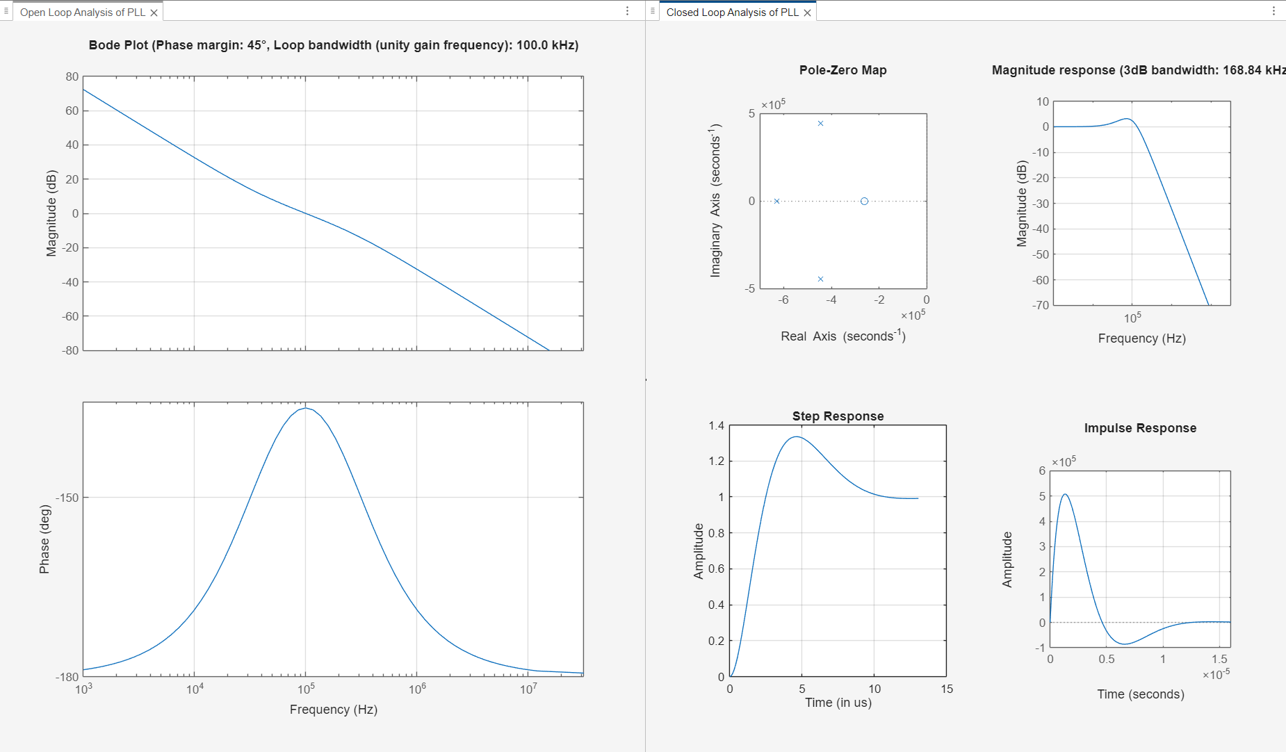
The model has the baseband PLL block configured for a loop filter of type 2nd order and has the block mask button to plot open and close loop responses for the system as shown below:
load_system('RFModelPLLPhaseNoise');
open_system('RFModelPLLPhaseNoise/Baseband PLL');
Clicking on 'Plot loop dynamic' button displays various plots that represent the characteristics of the PLL block analyzed as a control system:
Effect of Phase Noise in RF System Performance
To observe the role that phase noise plays in the overall RF system, we are considering following 3 cases of baseband signals being fed to the RF system:
Baseband signal without phase noise
Baseband signal with phase noise from reference oscillator
Baseband signal with phase noise filtered through a baseband PLL
In the model provided in the example, the reference oscillator subsystem generates a signal with a constant phase offset to which phase noise has been added. The Baseband PLL block applies the PLL's closed loop transfer function to this signal, producing an output with the same constant phase offset, but with filtered phase noise. The VCO output of this block is taken as the phase input to a block that converts amplitude and phase into a complex valued baseband signal.This is then converted to the RF Blockset complex signal envelope format (using an 'Inport' block from RF Blockset) and then to a complex baseband signal format by an 'Outport' block from RF Blockset. The baseband signal is then analyzed by a spectrum analyzer. The impact of the phase noise is also visible in the constellation diagram for all 3 cases listed above. To ease the comparison, the signal magnitude is same for all three cases.
sim("RFModelPLLPhaseNoise.slx");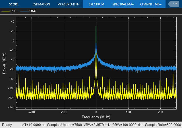
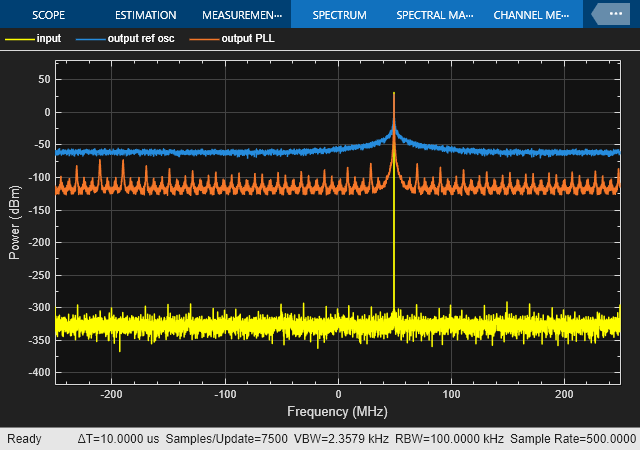
One can observe significant noise floor introduced for the case when baseband signal with phase noise was fed to the system. That gets improved by the use of baseband PLL which helps in filtering out most of the phase noise and hence dropping the noise floor in the overall spectrum.
Effect of Phase Noise on Frequency Synthesis for RF Systems
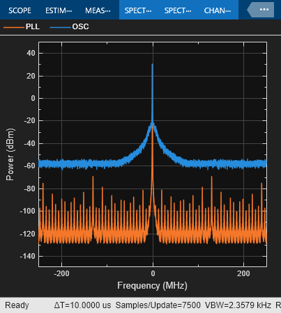
A second model allows to accurately model the effects of phase noise on frequency synthesis for wireless communications systems. In this model the same reference oscillator is used to drive a first upconverter mixer, and then 2 different PLLs each driving an additional upconverter stage. Notice that the phase noise of each stage is correlated as it is originated by the same oscillator. The PLLs have different loop filters, and the cumulative effects of phase noise and loop responses are measurable on the constellation of the output signal. Notice also that the actual frequency division is modeled in the RF Blockset Inports, allowing a faster simulation: the reference oscillator is at 2GHz, the output of second PLL at 4GHz, and the output of the third PLL at 10GHz.
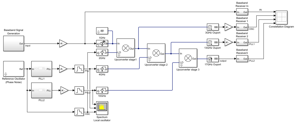
load_system('RFModelPLLFreqSynthesis');
sim('RFModelPLLFreqSynthesis');