VCO
(Not Recommended) Model voltage controlled oscillator
VCO will be removed in a future release. Use Ring Oscillator VCO block instead. For more information, see Version History.
Libraries:
Mixed-Signal Blockset /
PLL /
Building Blocks
Description
VCO or voltage controlled oscillator is a voltage to frequency converter. It produces an output square wave signal whose frequency is controlled by the voltage at the input vctrl port. The frequency of the output signal, F is determined either by:
where:
Kvco = voltage sensitivity (in Hz/V)
Vctrl = control voltage (in V)
Fo= free running frequency (in Hz)
or from linear interpolation using the mapping:
where:
Vctnl = vector of control voltages (in V)
Fout= vector of corresponding output frequencies (in Hz)
Ports
Input
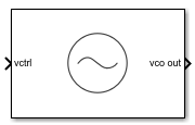
VCO control voltage used to control the output frequency of the VCO. In a phase-locked loop (PLL) system, vctrl is the output of the Loop Filter that contains the phase error information.
Data Types: double
Output
Output square wave signal of VCO. In a PLL system, vco out is the output clock generated by the PLL. It is also fed back to the PFD block through a clock divider to complete the control loop.
Data Types: double
Parameters
Parameters
Define how VCO output frequency is specified:
Select
Voltage sensitivityto specify output frequency from Voltage sensitivity (Hz/V) and Free running frequency (Hz).Select
Output frequency vs. control voltageto interpolate output frequency from Control voltage (V) vector versus Output frequency (Hz) vector.
Programmatic Use
Block parameter:
SpecifyUsing |
| Type: character vector |
Values:
Voltage sensitivity |
Output frequency vs. control
voltage |
Default:
Voltage sensitivity |
Measure of change in output frequency for input voltage change, specified as a positive real scalar with units in Hz/V. This parameter is also reported as VCO voltage sensitivity in the Loop Filter tab and is used to automatically calculate the filter component values of the loop filter.
Dependencies
To enable this parameter, select Voltage
sensitivity in Specify using
in the Parameters tab.
Programmatic Use
Block parameter:
Kvco |
| Type: character vector |
| Values: positive real scalar |
Default:
100e6 |
Data Types: double
Frequency of the VCO without any control voltage input
(0 V), or the quiescent frequency, specified as a
positive real scalar in Hz.
Dependencies
To enable this parameter, select Voltage
sensitivity in Specify using
in the Parameters tab.
Programmatic Use
Block parameter:
Fo |
| Type: character vector |
| Values: positive real scalar |
Default:
2.5e9 |
Data Types: double
Control voltage values of the VCO, specified as a real valued vector in volts.
Dependencies
To enable this parameter, select Output frequency vs.
control voltage in Specify
using in the Parameters
tab.
Programmatic Use
Block parameter:
ControlVoltage |
| Type: character vector |
| Values: real valued vector |
Default:
[-5 0 5] |
Data Types: double
Output frequency of the values of the VCO, corresponding to the Control voltage (V) vector, specified in Hz.
Dependencies
To enable this parameter, select Output frequency vs.
control voltage in Specify
using in the Parameters
tab.
Programmatic Use
Block parameter:
OutputFrequency |
| Type: character vector |
| Values: positive real valued vector |
Default:
[2e9 2.5e9 3e9] |
Data Types: double
Maximum amplitude of the VCO output voltage, specified as a positive real scalar.
Programmatic Use
Block parameter:
Amplitude |
| Type: character vector |
| Values: positive real scalar |
Default:
1 |
Data Types: double
Select to enable increased buffer size during simulation. This increases the buffer size of the Variable Pulse Delay block inside the VCO block. By default, this option is deselected.
Number of samples of the input buffering available during simulation, specified as a positive integer scalar. This sets the buffer size of the Variable Pulse Delay block inside the VCO block.
Selecting different simulation solver or sampling strategies can change the number of input samples needed to produce an accurate output sample. Set the Buffer size to a large enough value so that the input buffer contains all the input samples required.
Dependencies
To enable this parameter, select Enable increased buffer size.
Programmatic Use
Block parameter:
NBuffer |
| Type: character vector |
| Values: positive integer scalar |
Default:
10 |
Data Types: double
Impairments
Select to introduce phase noise as a function of frequency to the VCO. By default, this option is selected.
The frequency offsets of phase noise from the carrier frequency specified as a positive real valued vector in Hz.
Dependencies
To enable this parameter, select Add phase noise in the Impairments tab.
Programmatic Use
Block parameter:
Foffset |
| Type: character vector |
| Values: positive real valued vector |
Default:
[10e3 100e3 1e6 3e6 10e6] |
Data Types: double
The phase noise power in a 1 Hz bandwidth centered at the specified frequency offsets relative to the carrier specified as a negative real valued vector in dBc/Hz. The elements of Phase noise level corresponds to relative elements in the Phase noise frequency offset.
Dependencies
To enable this parameter, select Add phase noise in the Impairments tab.
Programmatic Use
Block parameter:
PhaseNoise |
| Type: character vector |
| Values: negative real valued vector |
Default:
[-77 -108 -134 -145 -154] |
Data Types: double
More About
The VCO subsystem block consists of two subsystems, Ideal VCO and Real VCO encapsulated under one variant subsystem.
If Add phase noise impairment is disabled, then the Ideal VCO subsystem gets active. This produces the following two orthogonal output signals, without any phase noise impairment and hence the name Ideal VCO:
Out of the two orthogonal outputs, only the real part of the signal, y1(t) is connected to the output port of VCO.
When the Add phase noise impairment is enabled, the Real VCO block becomes active which introduces phase noise as a function of frequency to the ideal VCO output. The subsystem consists of the Ideal VCO block with a phase noise generator block. The latter adds phase noise impairment to the input signal.
References
[1] Banerjee, Dean. PLL Performance, Simulation and Design. Indianapolis, IN: Dog Ear Publishing, 2006.
Version History
Introduced in R2019aVCO block will be removed in a future release. Use Ring Oscillator VCO block instead.
MATLAB Command
You clicked a link that corresponds to this MATLAB command:
Run the command by entering it in the MATLAB Command Window. Web browsers do not support MATLAB commands.
Select a Web Site
Choose a web site to get translated content where available and see local events and offers. Based on your location, we recommend that you select: .
You can also select a web site from the following list
How to Get Best Site Performance
Select the China site (in Chinese or English) for best site performance. Other MathWorks country sites are not optimized for visits from your location.
Americas
- América Latina (Español)
- Canada (English)
- United States (English)
Europe
- Belgium (English)
- Denmark (English)
- Deutschland (Deutsch)
- España (Español)
- Finland (English)
- France (Français)
- Ireland (English)
- Italia (Italiano)
- Luxembourg (English)
- Netherlands (English)
- Norway (English)
- Österreich (Deutsch)
- Portugal (English)
- Sweden (English)
- Switzerland
- United Kingdom (English)