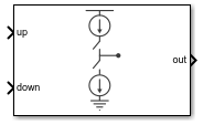
Charge Pump
Output a current proportional to the difference in duty cycle between two input ports
Libraries:
Mixed-Signal Blockset /
PLL /
Building Blocks
Description
The Charge Pump block produces an output current which is proportional to the difference in duty cycles between the signals at its up and down input ports. In a phase-locked loop (PLL) system, the Charge Pump block converts the phase error as represented by the two outputs of the PFD block into a single current at the input to the Loop Filter.
Ports
Input
Output
Output port, connected to the Loop Filter block in a PLL system. out delivers current proportional to the difference in duty cycles between up and down input ports.
Data Types: double
Parameters
Configuration
Full scale magnitude of design output current, specified as a positive real scalar in amperes. This parameter is tunable.
Programmatic Use
Use
get_param(gcb,'OutputCurrent')to view the current value of Output current (A).Use
set_param(gcb,'OutputCurrent',value)to set Output current (A) to a specific value.
Logic switching threshold at input ports, specified as a real scalar in volts.
Programmatic Use
Use
get_param(gcb,'InputThreshold')to view the current value of Input threshold (V).Use
set_param(gcb,'InputThreshold',value)to set Input threshold (V) to a specific value.
Select to enable increased buffer size during simulation. This increases the buffer size of the Logic Decision and Slew Rate inside the Charge Pump block. By default, this option is deselected.
Number of samples of the input buffering available during simulation, specified as a positive integer scalar. This sets the buffer size of the Logic Decision and Slew Rate inside the Charge Pump block.
Selecting different simulation solver or sampling strategies can change the number of input samples needed to produce an accurate output sample. Set the Buffer size to a large enough value so that the input buffer contains all the input samples required.
Dependencies
This parameter is only available when Enable increased buffer size option is selected in the Configuration tab.
Programmatic Use
Use
get_param(gcb,'NBuffer')to view the current value of Buffer size.Use
set_param(gcb,'NBuffer',value)to set Buffer size to a specific value.
Impairments
Select to add current impairments such as current imbalance and leakage current to simulation. By default, this option is selected.
Difference between full scale positive and negative current, specified as a positive real scalar in amperes.
Dependencies
To enable this parameter, select Enable current impairments in the Impairments tab.
Programmatic Use
Use
get_param(gcb,'CurrentImbalance')to view the current value of Current imbalance (A).Use
set_param(gcb,'CurrentImbalance',value)to set Current imbalance (A) to a specific value.
Data Types: double
Output current when both inputs are at logic zero, specified as a nonnegative real scalar in amperes.
Dependencies
To enable this parameter, select Enable current impairments in the Impairments tab.
Programmatic Use
Use
get_param(gcb,'LeakageCurrent')to view the current value of Leakage current (A).Use
set_param(gcb,'LeakageCurrent',value)to set Leakage current (A) to a specific value.
Data Types: double
Select to add timing impairments such as rise/fall time and propagation delay to simulation. By default, this option is selected.
Determine how output step size is calculated:
Select
Defaultto calculate output step size from rise/fall time. Output step size (ΔT) is given by .Select
Advancedto calculate output step size from maximum frequency of interest. Output step size (ΔT) is given by .
Dependencies
To enable this parameter, select Enable timing impairments in the Impairments tab.
Maximum frequency of interest at the output, specified as a positive real scalar in Hz.
Dependencies
To enable this parameter, select Enable timing impairments in the Impairments tab and choose Advanced for Output step size calculation.
Programmatic Use
Use
get_param(gcb,'MaxFreqInterest')to view the current value of Maximum frequency of interest (Hz).Use
set_param(gcb,'MaxFreqInterest',value)to set Maximum frequency of interest (Hz) to a specific value.
Data Types: double
up
20%-80% rise/fall time for up input port, specified as a positive real scalar in seconds.
Dependencies
To enable this parameter, select Enable timing Impairments in the Impairments tab.
Programmatic Use
Use
get_param(gcb,'RiseFallUp')to view the current value of up Rise/fall time.Use
set_param(gcb,'RiseFallUp',value)to set up Rise/fall time to a specific value.
Total propagation delay for up input port, specified as a positive real scalar in seconds.
Dependencies
To enable this parameter, select Enable Impairments in the Impairments tab.
Programmatic Use
Use
get_param(gcb,'PropDelayUp')to view the current value of Up propagation delay.Use
set_param(gcb,'PropDelayUp',value)to set Up propagation delay to a specific value.
down
20%-80% rise/fall time for down input port, specified as a positive real scalar in seconds.
Dependencies
To enable this parameter, select Enable Impairments in the Impairments tab.
Programmatic Use
Use
get_param(gcb,'RiseFallDown')to view the current value of down Rise/fall time.Use
set_param(gcb,'RiseFallDown',value)to set down Rise/fall time to a specific value.
Total propagation delay for down input port, specified as a positive real scalar in seconds.
Dependencies
To enable this parameter, select Enable Impairments in the Impairments tab.
Programmatic Use
Use
get_param(gcb,'PropDelayDown')to view the current value of Down propagation delay.Use
set_param(gcb,'PropDelayDown',value)to set Down propagation delay to a specific value.
More About
The Charge Pump block converts the two outputs of the PFD block into a single output. It consists of two current branches: one Up and one down. The difference between these two branches is summed to the leakage current impairment, if enabled.
Each current branch consists of a Logic Decision block, an Impairments subsystem, and a gain block. The Logic Decision block compares the incoming signal to the Input Threshold. The Impairments subsystem incorporates the effect of the charge pump impairments. The gain block multiplies the output of the Impairments subsystem to produce the current level defined in the Output current parameter.
References
[1] Banerjee, Dean. PLL Performance, Simulation and Design. Indianapolis, IN: Dog Ear Publishing, 2006.
[2] Gardner, Floyd M. Phaselock Techniques. Hoboken, NJ: John Wiley & Sons, Inc. 2005.
Version History
Introduced in R2019a
See Also
MATLAB Command
You clicked a link that corresponds to this MATLAB command:
Run the command by entering it in the MATLAB Command Window. Web browsers do not support MATLAB commands.
Select a Web Site
Choose a web site to get translated content where available and see local events and offers. Based on your location, we recommend that you select: .
You can also select a web site from the following list
How to Get Best Site Performance
Select the China site (in Chinese or English) for best site performance. Other MathWorks country sites are not optimized for visits from your location.
Americas
- América Latina (Español)
- Canada (English)
- United States (English)
Europe
- Belgium (English)
- Denmark (English)
- Deutschland (Deutsch)
- España (Español)
- Finland (English)
- France (Français)
- Ireland (English)
- Italia (Italiano)
- Luxembourg (English)
- Netherlands (English)
- Norway (English)
- Österreich (Deutsch)
- Portugal (English)
- Sweden (English)
- Switzerland
- United Kingdom (English)