Main Content

Inverse Clarke Transform

Implement αβ to abc transformation

Since R2020a

Libraries:
Motor Control Blockset / Controls / Math Transforms
Motor Control Blockset HDL Support / Controls / Math Transforms

Description

The Inverse Clarke Transform block computes the Inverse Clarke transformation of balanced, two-phase orthogonal components in the stationary αβ reference frame and outputs the balanced, three-phase components in the stationary abc reference frame. Alternatively, the block can compute Inverse Clarke transformation of the components α, β, and 0 to output the three-phase components a, b, and c. For a balanced system, the zero component is equal to zero. Use the Number of inputs parameter to use either two or three inputs.

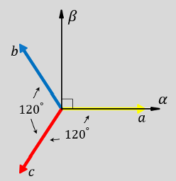
The block accepts the α-β axis components as inputs and outputs the corresponding three-phase signals, where the phase-a axis aligns with the α-axis.

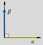
  • The α and β input components in the αβ reference frame.
  • The direction of the equivalent a, b, and c output components in the abc reference frame and the αβ reference frame.
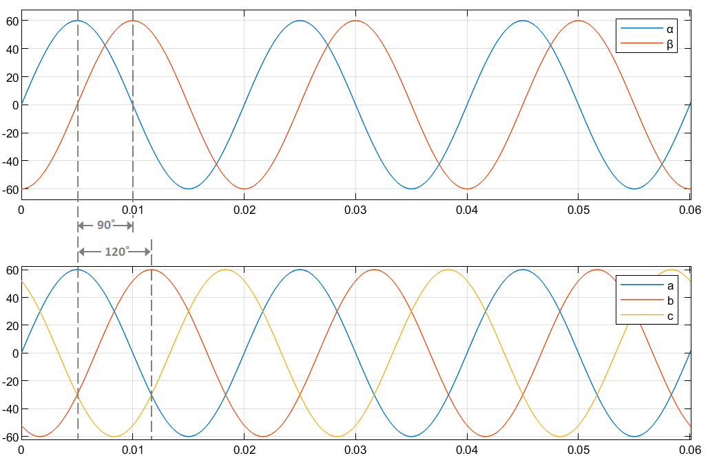
  • The time-response of the individual components of equivalent balanced αβ and abc systems.
Equations

The following equation describes the Inverse Clarke transform computation:

[fafbfc]=[1011232112321][fαfβf0]

For balanced systems like motors, the zero sequence component calculation is always zero:

ia+ib+ic=0

Therefore, you can use only two current sensors in three-phase motor drives, where you can calculate the third phase as,

ic=(ia+ib)

By using these equations, the block implements the Inverse Clarke transform as,

[fa fb fc ]= [1012321232][fαfβ] 

where:

  • fα and fβ are the balanced two-phase orthogonal components in the stationary αβ reference frame.

  • f0 is the zero component in the stationary αβ reference frame.

  • fa, fb, and fc are the balanced three-phase components in the abc reference frame.

Ports

Input

expand all

Alpha-axis component, α, in the stationary αβ reference frame.

Dependencies

To enable this port, set the Number of inputs parameter to Two inputs.

Data Types: single | double | fixed point

Beta-axis component, β, in the stationary αβ reference frame.

Dependencies

To enable this port, set the Number of inputs parameter to Two inputs.

Data Types: single | double | fixed point

Multiplexed alpha-axis component, α and beta-axis component, β and 0 component, in the stationary αβ reference frame.

Dependencies

To enable this port, set the Number of inputs parameter to Three inputs.

Data Types: single | double | fixed point

Output

expand all

Component of the three-phase system in the abc reference frame.

Dependencies

To enable this port, set the Number of inputs parameter to Two inputs.

Data Types: single | double | fixed point

Component of the three-phase system in the abc reference frame.

Dependencies

To enable this port, set the Number of inputs parameter to Two inputs.

Data Types: single | double | fixed point

Component of the three-phase system in the abc reference frame.

Dependencies

To enable this port, set the Number of inputs parameter to Two inputs.

Data Types: single | double | fixed point

Multiplexed phase components a,b, and c of the three-phase system in the abc reference frame.

Dependencies

To enable this port, set the Number of inputs parameter to Three inputs.

Data Types: single | double | fixed point

Parameters

expand all

Select the number of inputs that you can specify:

  • Two inputs — Configure the block to accept two separate input signals α and β. The block generates three separate output signals a, b, and c.

  • Three inputs — Configure the block to accept a multiplexed input containing α, β, and 0 signals. The block generates a multiplexed output containing a,b, and c signals.

To enable the power invariance property in the block output, select this parameter. To disable power invariance (enable amplitude invariance) in the block output, clear this parameter.

Extended Capabilities

C/C++ Code Generation
Generate C and C++ code using Simulink® Coder™.

Fixed-Point Conversion
Design and simulate fixed-point systems using Fixed-Point Designer™.

Version History

Introduced in R2020a

Go to top of page