Field-Weakening Control (with MTPA) of Nonlinear Synchronous Reluctance Motors Using Lookup Table
This example uses a lookup table (LUT) for a nonlinear synchronous reluctance motor and controller to run the motor using field-weakening control (with maximum torque per ampere (MTPA)). Use this example to replicate and run a finite element analysis (FEA) based nonlinear, high-fidelity synchronous reluctance motor in simulation. This example helps motor design engineers to simulate high-performance motors in real-world motor control applications. In addition, control system engineers can use this example to design control algorithms for a given set of motor parameter data to achieve high levels of accuracy in tracking and controlling speed and torque as well as to meet efficiency requirements, especially for high-performance motors.
This image shows the MTPA and field-weakening operating points for a synchronous reluctance motor.

(The preceding image is for illustration purposes only and is not to scale.)
Traditionally, to generate optimal reference current data you required an actual motor and hardware in a dyno setup. But using an actual synchronous reluctance motor and hardware to design a motor as well as the control algorithm can be impractical due to higher operation costs and time, safety issues, as well as sporadic machine and inverter failures. This example effectively solves these problems by using a simulation-based model driven by an LUT that contains motor parameter data. It uses an LUT that contains Ld and Lq data with respect to currents id and iq.
The example uses the LUT based SynRM Control Reference block that utilizes the synchronous reluctance motor's nonlinear inductance and permanent magnet flux linkage data to design and implement flux-weakening torque control id (torque, speed) and iq (torque, speed) LUTs by using iterative analytical methods.
By default, this example uses the motor characterization data generated from the lumped parameter values. However, as an alternative, you can configure the LUT based SynRM Control Reference block and generate your own reference current id (torque, speed) and iq (torque, speed) LUT and use it in the same example.
You can use the example to simulate the LUT-based motor model and run tests to design the control algorithm. This enables you to run challenging tests easily and perform robust machine and control algorithm validation, which in turn reduces the time required for hardware testing and saves the overall development time.
You can use precalibrated reference current LUT data files for nonlinear synchronous reluctance motors in the example model. Because solving the underlying motor equations for nonlinear high-performance motors is computationally intensive, the example relies on LUTs generated by solving these (non-approximated) equations. This enables you to run control algorithms on the controller hardware with high accuracy (because LUT data mimics the actual nonlinear motor characteristics).
Using this approach, you can reduce the complexities that occur when the algorithm relies on the controller hardware to solve approximated equations for nonlinear synchronous reluctance motor.
The example helps you build a field-weakening (with MTPA) control algorithm that can compensate for the reduced torque caused by nonlinearity resulting from a magnetically saturated synchronous reluctance motor stator core.
For more details about these operating regions, see SynRM Constraint Curves and Their Application.
Model
This example includes the mcb_synrm_nonlin_fwc Simulink® model.
You can use this model only for simulation.
Required MathWorks Products
Motor Control Blockset™
Simscape™ Electrical™ or Powertrain Blockset™
About LUT Data File
By default, the example uses the following LUT data file, which is loaded and read by the model initialization script mcb_synrm_nonlin_fwc_data associated with the example model:
For more details, see the System Parameters section of the model initialization script.
The following blocks in the example model use the loaded LUT data:
mcb_synrm_nonlin_fwc/Control System/Torque Control/LUT based SynRM Control Reference— Uses the reference current LUTs derived from the inductance LUTs.

mcb_synrm_nonlin_fwc/Control System/Torque Control/Control_System/Current_Controllers/SynRM FeedForward Control— Uses the inductance LUTs.

mcb_synrm_nonlin_fwc/Inverter and Motor/Variant Subsystem/
- Simscape — This motor model uses a switching inverter with Synchronous Reluctance Machine (Simscape Electrical) block from Simscape Electrical that uses 2-D motor characterization data (Ld(id,iq), Lq(id,iq)) tables from the loaded .mat file.
- PTBS — This motor model uses an average inverter with Flux-Based PMSM (Powertrain Blockset) block from Powertrain Blockset that uses 2-D motor characterization data (id(ψd,ψq), iq(ψd,ψq)) from the loaded .mat file (where, ψd and ψq are the d-axis and q-axis flux linkages, respectively).
Simulate Model
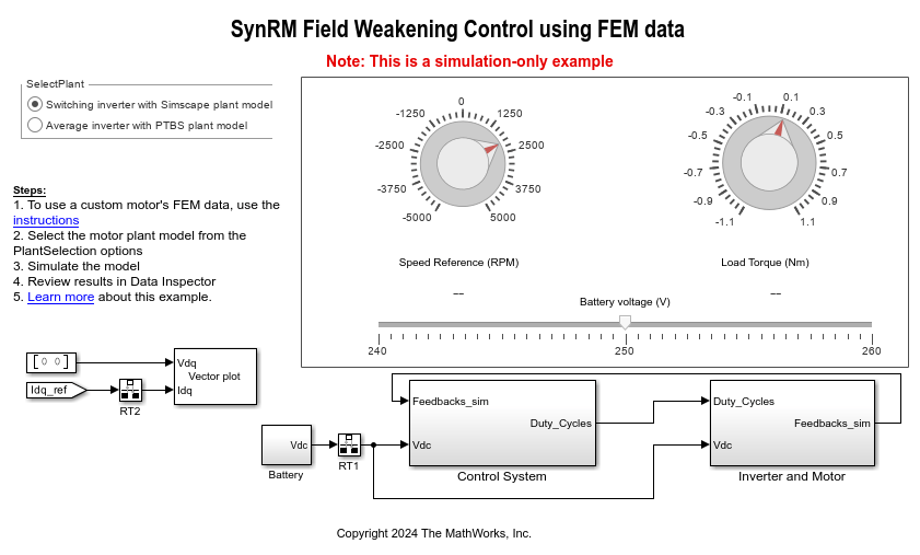
1. Open the Simulink model mcb_synrm_nonlin_fwc associated with this example.
2. Use the SelectPlant radio button in the example model to select the motor model that you want to simulate using the LUT data:
a. Switching inverter with Simscape plant model
b. Average inverter with PTBS plant model
3. Click Run on the Simulation tab to simulate the model.
4. Set the reference speed and load torque values using the Speed Reference (RPM) and Load Torque (Nm) knobs.
5. Click Data Inspector on the Simulation tab to view and analyze the simulation results.
Note: Use the slide bar in the model to simulate the example using a different operating voltage of a battery (to match real-life conditions).
Generate LUT Data File for Custom Motor Design
The following procedure explains the steps needed to obtain the inductance LUT data set (either manually generated or downloaded from JMAG) and use it with the same or a similar example model.
Note: The motor model data from JMAG uses an axis notation that is identical to that of a PMSM. Therefore, the following procedure uses the Motor Control Blockset utility functions specifically created for PMSMs.
1. Obtain the .rtt file and RT-Viewer tool:
a. Download the LUT data set (.rtt file) for your motor from the JMAG-RT Model Library. The data set includes the Ld and Lq maps.
Note: Downloading and using this file requires Type-2 (free) license that you can obtain by requesting for it.
b. Click JMAG-RT Viewer to obtain the RT-Viewer tool.
2. Use the RT Viewer tool to open the .rtt file and export the Ld and Lq table values into an identical grid of the id and iq values. For example, save the Ld and Lq table values as JMAG_Ld.csv and JMAG_Lq.csv.
a. In the RT Viewer tool menu, select Table Value > Inductance > Id-Iq-Ld.
b. In the Map Window menu, select File > CSV Export to open the CSV Export window.
c. In the CSV Export window, provide id and iq grid details and the file name to proceed with the data export.
Note: If you have a manually-generated LUT data set, skip steps numbered 1 and 2.
3. In the model initialization script associated with the Simulink model, create template structures for the SynRM and inverter as shown below:
motor = mcb_SetPMSMMotorParameters('Teknic2310P');
inverter = mcb_SetInverterParameters("BoostXL-DRV8305");
motor.B = motor.B*100;
4. In the script, find the motor parameters and update the following fields:
motor.p (pole pairs)
motor.Rs (stator/coil resistance)
motor.Ld (d_inductance)
motor.Lq (q_inductance)
motor.J (inertia)
motor.I_rated (rated_current)
inverter.V_dc (rated_voltage)
5. Calculate the rated torque value using the following function:
motor.T_rated = mcbPMSMRatedTorque(motor, inverter);
6. Create a seed structure with the file paths to read the .csv files that you created in step 2.
seed.Ldfilepath = 'JMAG_Ld.csv';
seed.Lqfilepath = 'JMAG_Lq.csv';
Note: If you are using a manually-generated inductance LUT data set, use the paths to the associated .csv files instead.
7. Create LUTs using the following API:
PMSMLUT = mcbGenerateTables(motor,inverter,'jmagindfiles2inddq',seed);
This command converts the .csv files generated by the JMAG-RT Viewer into a regular matrix, filling the empty places using extrapolation.
8. Configure the following blocks in the example model to use the nonlinear LUTs:
- LUT based SynRM Control Reference — In the block dialog box, set the Motor parameter input method parameter to Non-linear model with id and iq LUTs.
- SynRM FeedForward Control — In the block dialog box, set the Motor parameter input method parameter to Non-linear model with Ld and Lq LUTs.
- SynRM Torque Estimator — In the block dialog box, set the Motor parameter input method parameter to Non-linear model with Ld and Lq LUTs.
9. In the example model, create a plant using the Synchronous Reluctance Machine (Simscape Electrical) block.
10. In the Synchronous Reluctance Machine block dialog box, set the Modelling option parameter to No thermal port.
11. Set Stator parameterization to Specify Ld, Lq, and L0 as well as Modeling fidelity to Tabulated Ld and Lq. Provide the LUT.idVec, LUT.idVec, LUT.LdTable, and LUT.LqTable along with the motor parameters motor.p and motor.Rs in their respective fields.
Under Mechanical drop-down menu, provide motor.J and motor.B with the appropriate Rotor angle definition.
12. To generate the id and iq LUTs from inductance LUT data, use the following command:
LUT=mcbGenerateTables(motor,inverter,'idiqLUTs',seed);
For more details about the structure of the variable seed, use the MATLAB command help for mcbGenerateTables.
Alternatively, you can also use Model-Based Calibration Toolbox™ to calibrate the PMSM or SynRM and generate the id and iq LUTs. For more information see Preprocess Permanent Magnet Synchronous Motor (PMSM) Data and Autogenerate Current Controller Calibration Tables (Model-Based Calibration Toolbox).
13. In the model initialization script, populate the SynRM LUT fields at appropriate places in the LUT based SynRM Control Reference block depending on the parameter input method:
LUT.idVec
LUT.iqVec
LUT.LdTable
LUT.LqTable
or
LUT.trefVec
LUT.wrpmVec
LUT.idTable
LUT.iqTable
14. Similarly, populate the rest of the motor parameters at their respective places.
15. For the SynRM plant model:
- Maintain the default value for the stator zero sequence inductance.
- Update the variables motor.B and motor.J in the mechanical parameters section.
- Set initial targets for rotor speed and rotor position to 0.
Note: For the complete set of commands to execute the preceding steps for motor models from Simscape as well as PTBS, see the model initialization script mcb_synrm_nonlin_fwc_data associated with the example.