Apply Configurations to Optical System Imported from ZMX File
This example shows to apply preset configurations from a ZMX file to the optical design stored in the ZMX file.
A ZMX file contains the optical design of a photographic lens system. The file also contains multiple preset configurations, also referred to as multi-configuration, that give you the flexibility to explore and manage design variations of the optical system using a single file. You can apply the configurations and create a distinct optical system by dynamically adjusting properties of components in the optical system, such as surface curvature, thickness, material, and aperture. Common applications of multiple configurations include zoom lenses, color correction, tolerancing, and environmental analysis.
This example requires the Optical Design and Simulation Library for Image Processing Toolbox™. You can install the Optical Design and Simulation Library for Image Processing Toolbox from Add-On Explorer. For more information about installing add-ons, see Get and Manage Add-Ons.
Read Multiple Configurations of ZMX File
This example uses the ZMX file for photographic zooms created and converted by Bill Claff and shared on the Lens Design website [1].
Read the metadata of the ZMX file.
fileName = "PhotographicLens.zmx";
info = zmxinfo(fileName)
info = struct with fields:
Filename: 'C:\Users\Example\PhotographicLens.zmx'
Version: "161019 507 33785"
Mode: "SEQ"
Name: "CN 108535851 Example 1 (Venus Laowa 10-18mm f4.5-5.6 Zoom)"
Units: [1×1 struct]
FieldPoints: [3×1 optics.fieldpoint.FieldPosition]
Wavelengths: [486.1327 587.5618 656.2725]
PrimaryWavelength: 587.5618
GlassCatalog: [0×0 struct]
Surfaces: [30×1 struct]
ParaxialInfo: [1×1 struct]
SurfaceConfigurations: [30×4 table]
RawTags: [1×1 struct]
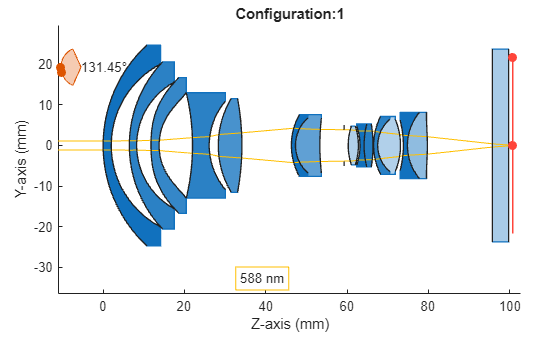
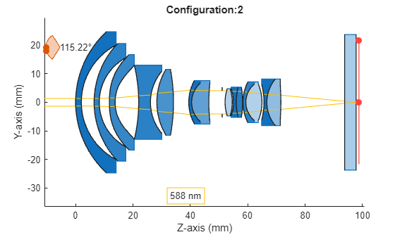
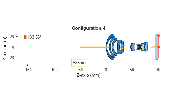
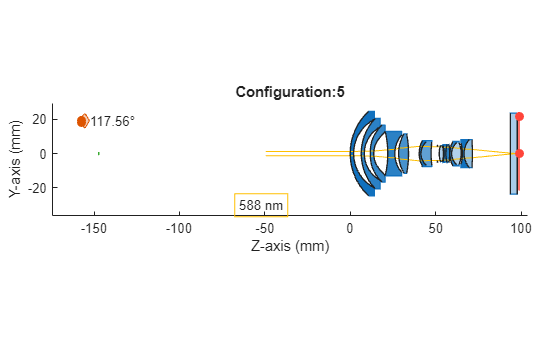
Extract the multiple configurations in the ZMX file to the variable configInfo. Each row in the configInfo table provides specific data for a given configuration and surface, describing one of the properties, such as semi-diameter or distance to the next optical component, and the corresponding value of the property. You can modify the properties of surfaces that are physically adjustable, such as the semi-diameter of a diaphragm, while fixed properties like the optical material or dimensions of a lens element remain unchangeable. The multi-configuration functionality allows adjustments exclusively for the parameters that are alterable in a real-world setup. For example, the first row in the table indicates that, in the first configuration, the surface with index 14, which is a diaphragm, has a semi diameter of 3.862 units. Each row in the table shows how different properties change for different surfaces in different configurations. The configurations in this optical system show the lens arrangement for different zoom levels of the photographic lens system.
configInfo = info.SurfaceConfigurations;
disp(configInfo)
    ConfigurationIndex    SurfaceIndex        Property        Value
    __________________    ____________    ________________    ______

            1                  14         "SemiDiameter"      3.8625
            1                   0         "DistanceToNext"     1e+10
            1                  10         "DistanceToNext"     12.18
            1                  13         "DistanceToNext"    5.9744
            1                  26         "DistanceToNext"        16
            2                  14         "SemiDiameter"      4.0525
            2                   0         "DistanceToNext"     1e+10
            2                  10         "DistanceToNext"    5.3205
            2                  13         "DistanceToNext"    4.6647
            2                  26         "DistanceToNext"    22.225
            3                  14         "SemiDiameter"       4.243
            3                   0         "DistanceToNext"     1e+10
            3                  10         "DistanceToNext"       1.5
            3                  13         "DistanceToNext"    3.8391
            3                  26         "DistanceToNext"    28.032
            4                  14         "SemiDiameter"      3.8625
            4                   0         "DistanceToNext"    145.25
            4                  10         "DistanceToNext"    13.136
            4                  13         "DistanceToNext"    5.0185
            4                  26         "DistanceToNext"    16.015
            5                  14         "SemiDiameter"      4.0525
            5                   0         "DistanceToNext"     147.2
            5                  10         "DistanceToNext"    6.2503
            5                  13         "DistanceToNext"    3.7349
            5                  26         "DistanceToNext"    22.252
            6                  14         "SemiDiameter"       4.243
            6                   0         "DistanceToNext"    146.04
            6                  10         "DistanceToNext"    2.4453
            6                  13         "DistanceToNext"    2.8938
            6                  26         "DistanceToNext"    28.075
Compute the number of distinct configurations in the table. Observe that the ZMX file contains six configurations representing six distinct zoom levels.
uniqueConfigIdx = unique(configInfo.ConfigurationIndex);
numConfigs = numel(uniqueConfigIdx)
numConfigs =
6
Apply Configurations to Optical System
Apply the configurations to the optical system opsys using the applyConfiguration helper function, provided at the end of this example. Visualize rays traced through the optical system.
[opsys,~,surfaceIdxMap] = zmximport(fileName);
Use the Surface Index Map, surfaceIdxMap, to get the surface index of the optical system corresponding to the surface index specified in the ZMX file.
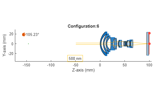
fp = fieldPoint;
lambda = opsys.PrimaryWavelength;
for configIdx = 1:numConfigs
    applyConfiguration(opsys,surfaceIdxMap,configInfo,configIdx);
    titletxt = "Configuration:" + string(configIdx);
    f = figure;
    h = view2d(opsys,Title=titletxt,Parent=f);
    rb = traceMarginalRays(opsys,FieldPoint=fp,Wavelengths=lambda);
    addRays(h,rb)
end

Create Intermediate Configurations
The configuration indices for this optical system indicate zoom levels. You can create intermediate zoom levels by interpolating surface properties between the values of the preset configurations. For example, you can achieve a zoom level of 3.7 by interpolating the values of the semi-diameter and distance to the next optical component between the values represented in configurations 3 and 4.
Use the zoomLevel slider to adjust the zoom level value and transition between zoom levels.
zoomLevel =  4.2;
4.2;Create an intermediate configuration for the specified zoom level using the applyConfiguration helper function, provided at the end of this example. Visualize the optical system for the intermediate zoom level.
applyConfiguration(opsys,surfaceIdxMap,configInfo,zoomLevel);
titletxt = "Zoom Level:" + string(zoomLevel);
f = figure;
h = view2d(opsys,Title=titletxt,Parent=f);
rb = traceMarginalRays(opsys,FieldPoint=fp,Wavelengths=lambda);
addRays(h,rb)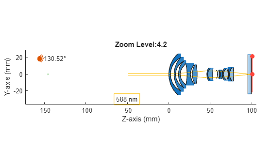
Supporting Function
The applyConfiguration helper function applies the preset configuration to the optical system opsys if the configuration index configIdx exists in the preset configurations. If the configuration index does not exist in the preset configurations, the function interpolates the surface properties for the configuration index using the surface properties of the preset configurations, and applies the interpolated configuration to the optical system opsys.
function applyConfiguration(opsys,surfaceIdxMap,configInfo,configIndx)
% Helper function that updates the positions/semi-diameters of an optical
% system based on configurations stored in ZMX file. This code is part of
% the Update Configurations example being shipped with Optics.
    sIndices = unique(configInfo.SurfaceIndex);
    % From the surface index map, get the surface index in the optical
    % system corresponding to the surface index in the zmx file.
    fileIndexMap = surfaceIdxMap.File2OpticalSystem;
    for indx = 1:numel(sIndices)
        sInd = sIndices(indx);
        % Extract the surface configurations for surface index sInd
        surfInfo = configInfo(configInfo.SurfaceIndex == sInd,:);
        sValue = interp1(surfInfo.ConfigurationIndex, surfInfo.Value, configIndx);
        property = surfInfo(surfInfo.ConfigurationIndex == floor(configIndx),:).Property;
        if sInd == 0
            opsysSurfIndx= sInd;
        else
            opsysSurfIndx = fileIndexMap(sInd);
        end
        switch property
            case "DistanceToNext"

                if opsysSurfIndx==0 % Object plane
                    if sValue < 1e5 % Object planes at finite distance
                        opsys.ObjectPlane.Position = [0 0 -sValue];
                    else % Object planes at infinite distance
                        % zmx files have 1e10 for infinite distance
                        opsys.ObjectPlane.Position = [0 0 -Inf];
                    end
                    continue;
                end
                % Change the distance to next for the surface sInd by getting
                % its component.

                % Get the component index
                cInd = opsys.SurfaceTable(opsysSurfIndx,:).ComponentIndex;

                % Extract the rows that belong to this component
                cmpSurfTable = opsys.SurfaceTable( ...
                    (opsys.SurfaceTable.ComponentIndex == cInd),:);

                % Find the position of the surface sInd is the component
                sIndInComponent = find(cmpSurfTable.Index == opsysSurfIndx);


                if sIndInComponent == numel(opsys.Components(cInd).Surfaces)
                    % It is the last surface of the component.
                    % use changeGap to change the gap after this component.
                    changeGap(opsys, cInd, sValue);
                else
                    % It is not the last surface of the
                    % component, change the thickness of the component
                    % immediately after this surface
                    opsys.Components(cInd).Thickness(sIndInComponent) = sValue;
                end
            case "SemiDiameter"
                if (opsysSurfIndx==0) % Object plane
                    opsys.ObjectPlane.Shape.SemiDiameter = sValue;
                    continue;
                end
                % Change the semidiameter of the surface sInd
                opsys.Surfaces(opsysSurfIndx).Shape.SemiDiameter = sValue;
        end
    end
end
References
[1] The ZMX file for photographic zooms was created and converted by Bill Claff, shared on his website Photons to Photos (https://www.photonstophotos.net/) and hosted on the Lens Design repository (https://www.lens-designs.com/photographic-zooms).