Get Started with OPC UA in Simulink
R2026bThis example shows how to read and write data to nodes available on an OPC Unified Architecture (UA) server using Simulink® blocks from Industrial Communication Toolbox™. You can connect to the server using a Simulink model that acts as an OPC UA client. You can perform read and write operations in the model using the OPC UA Read and OPC UA Write blocks.
Set Up Server
To run this example in your MATLAB® session, you must install and start the Prosys OPC UA Simulation Server. For more information, see Install an OPC UA Simulation Server for OPC UA Examples.
Configure OPC UA Client in Simulink
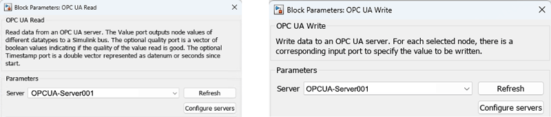
You can use the OPC Configuration pane to add, delete, connect, disconnect, and configure OPC UA clients. To enable the OPC Configuration pane, include either an OPC UA Read or OPC UA Write block in a new Simulink model. To open the OPC Configuration pane, click Configure Servers in the Block Parameters dialog box. You can open the Block Parameters dialog box or the block mask by double-clicking the OPC UA Read or OPC UA Write block. For more information on using the pane, see Configure OPC UA Client in Simulink.
After you create and connect to an OPC UA client, click Refresh to update the block with the new client information. Select the Server from the drop-down list to associate the block with the corresponding OPC UA client.
Add Node to OPC UA Blocks
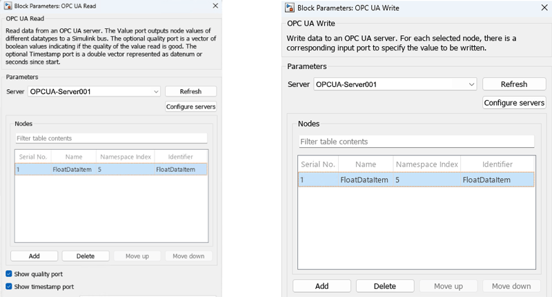
Open the Browse Namespace dialog box by clicking Add in the block mask. In the dialog box, select and add the variable nodes. This action updates the nodes table with the information about the added nodes. Delete a node from the table using Delete. Organize the nodes in the table using Move Up or Move Down. Add more nodes to the table using Add.
This example adds one node with the name FloatDataItem and identifier FloatDataItem in the OPC UA Read as well as the OPC UA Write block.
Model Description
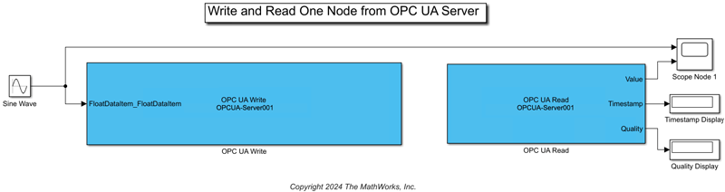
This image shows a model where an OPC UA Write and an OPC UA Read block are configured to write to and read from the node named FloatDataItem. This model writes the signal from the Sine Wave block to the OPC UA node FloatDataItem and reads the value at the node FloatDataItem. You can view the read values along with the original Sine Wave signal using a Scope block. You can view the timestamp and quality of the read data using the Display block. In this example, the Value port of the OPC UA Read block is a scalar Simulink signal as the block reads data from one node.
Visualize Simulation Results
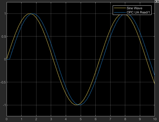
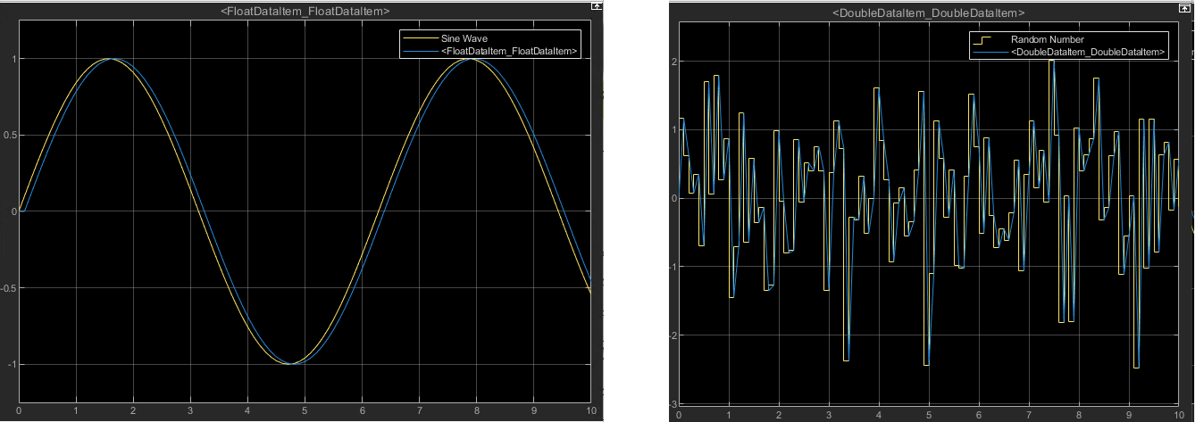
The priority of the OPC UA Write block is set higher than the OPC UA Read block to ensure that the write operation occurs before the read operation. This results in one sample delay between the transmitted and read sine wave signal.
Add More Nodes to OPC UA Blocks
Add nodes to a OPC UA Read or OPC UA Write block by clicking Add in the block mask. This example adds a second node with the name DoubleDataItem and identifier DoubleDataItem in the OPC UA Read as well as the OPC UA Write block.
Note: You can add nodes of different data types to a single OPC UA Read block as the block outputs a Simulink bus signal, which retains the data type of individual node data.
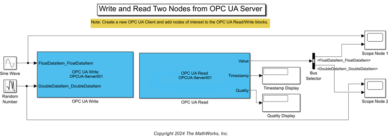
Use Bus Selector to Demux Node Value
When you use the OPC UA Read block to read more than one node from the OPC UA server, the Value port outputs a Simulink bus signal. You can use a Bus Selector (Simulink) to obtain individual values of the nodes. The BasicOPCUAModel provided with this example uses a Bus Selector block to view the data read from the two selected nodes in two separate Scope blocks.
The read and write signals have one sample delay between them due to the higher priority of write operation in the OPC UA blocks.
Extend the Example
This example uses a Prosys OPC UA Simulation Server configured with specific nodes. You can read from or write to the nodes available on any accessible OPC UA server using the OPC UA Read and OPC UA Write blocks.

