Front-Loader Actuation System
Warning: This example uses the hydraulic domain, which will be removed in a future release. Find an equivalent example model that uses the isothermal liquid domain here: Front-Loader Actuation System. To convert models to the isothermal liquid domain, use the hydraulicToIsothermalLiquid tool.
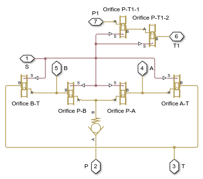
This example shows a simplified version of an actuation system consisting of the lift and tilt cylinders. Each cylinder is controlled by an open center, 6-way, 3-position directional valve. The valves are connected in series through their unloading branch such that the system pump is unloaded when both command levers are in neutral position. If either tilt or lift command is applied, the unloading path is closed.
The pump is driven by a diesel engine simulated with a model that accounts for velocity change caused by the load on the output shaft. The directional valve is a custom model composed of Orifice with Variable Area Round Holes blocks and a Check Valve block.
A typical cycle of a front-loader actuation system is simulated with all the motion and load commands generated as a function of time.
Model

Lift Valve Subsystem

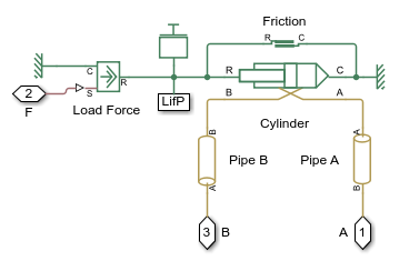
Lift Actuator Subsystem

Simulation Results from Simscape Logging
The plots below show the pressure difference in the lift and tilt cylinders and the position of the in each cylinder.
