Flow Divider Test Rig
Warning: This example uses the hydraulic domain, which will be removed in a future release. Find an equivalent example model that uses the isothermal liquid domain here: Flow Divider. To convert models to the isothermal liquid domain, use the hydraulicToIsothermalLiquid tool.
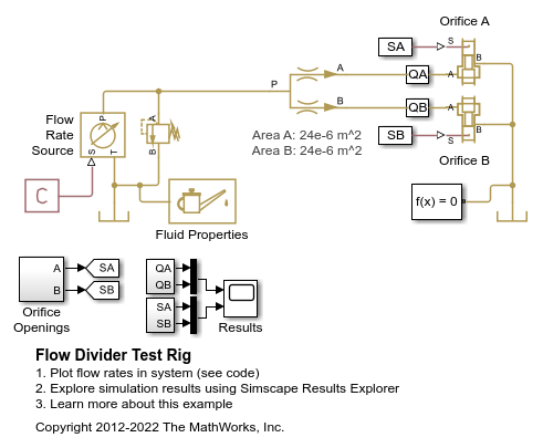
This example shows the behavior of a flow divider subjected to varying loads. The model consists of a power unit, flow divider, and two consumers. The power unit is modeled using a flow rate source and a pressure relief valve. The Flow Divider block splits the flow between the two variable orifices.
To test the ability of the Flow Divider block to split the flow equally between the two consumers, the load in the branches is varied by changing the passage area of the load orifices.
Model

Simulation Results from Simscape Logging
The plots below show the behavior of the flow divider as the load on each branch is varied. The flow divider manages to divide the flow nearly equal to the ratio of the flow divider orifice areas for the entire simulation. Near the end, the restrictions downstream of the flow divider become high enough that flow is diverted through the pressure relief valve.
