Reversible Heat Pump
This example shows a refrigeration cycle that can operate in heat pump mode for heating and in air conditioning mode for cooling. The refrigerant is R-410A. The system consists of a compressor, an outdoor heat exchanger, an electronic expansion valve (EXV), an indoor heat exchanger, and an accumulator. A 4-way directional valve separates the compressor and accumulator from the rest of the system to control the refrigerant flow direction.
In heat pump mode, the refrigerant to the left of the directional valve flows clockwise in the diagram. The hot refrigerant first passes through the indoor heat exchanger, which acts as a condenser, to transfer heat to the house. The EXV then expands the refrigerant to reduce its temperature. Finally, the cold refrigerant passes through the outdoor heat exchanger, which acts as an evaporator, to absorb heat from the environment. The component sizing is based on the heat pump mode operating conditions because it is expected to be more demanding than the air conditioning mode operating conditions.
In air conditioning mode, the refrigerant to the left of the directional valve flows counterclockwise in the diagram. The hot refrigerant first passes through the outdoor heat exchanger, which acts as a condenser, to reject heat to the environment. The EXV then expands the refrigerant to reduce its temperature. Finally, the cold refrigerant passes through the indoor heat exchanger, which acts as an evaporator, to transfer heat from the house to the refrigerant. Because the heat exchangers are sized for the heat pump mode operating conditions, they are likely over-sized for the air conditioning mode operating conditions.
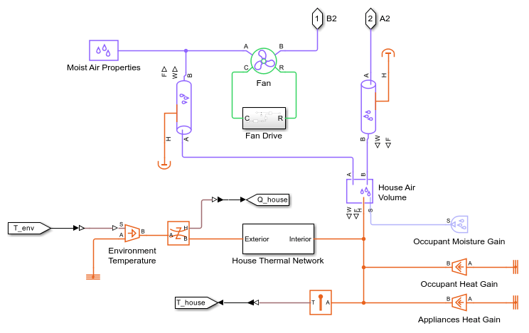
The thermal load in this model is the house, which is represented as a volume of air in the moist air domain. A thermal network models heat transfer between the external environment and the air in the house via the walls, roof, and windows. Additionally, occupants and appliances generate heat inside the house. A fan circulates air between the house and the indoor heat exchanger.
The simulation starts with a cold external environment at -10 degC and a relatively cold house at 16 degC. After 3 hours, the external temperature gradually rises to a hot external environment at 35 degC. The house temperature setpoint is 21 degC. The system starts in heat pump mode and then switches to air conditioning mode at around t = 2.31e4 seconds or 6.4 hours.
Model

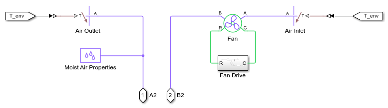
External Environment Subsystem
House Subsystem
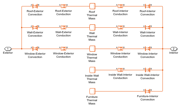
House Thermal Network Subsystem
Control Subsystem
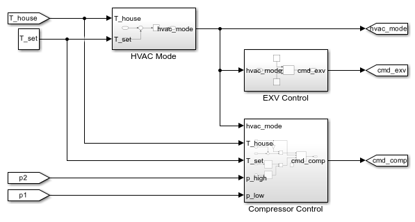
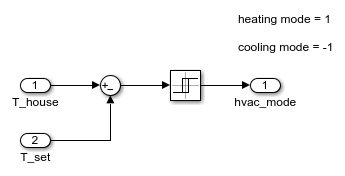
HVAC Mode Subsystem
The controller uses a relay to switch to heating mode when the house temperature is colder than the setpoint by 1 degC and to cooling mode when the house temperature is hotter than the setpoint by 1 degC.
Directional Valve Control Subsystem
The directional valve controls the refrigerant flow direction based on whether the system is in heating mode or cooling mode. However, when the compressor shuts down, the directional valve moves to the neutral position of 0.
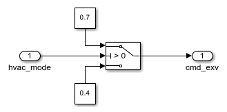
EXV Control Subsystem
The simplified control for the electronic expansion valve (EXV) is tied to the compressor command with a delay. The EXV opens more when the compressor ramps up and opens less when the compressor ramps down. This allows the system to maintain some subcooling when operating at partial capacity.
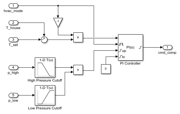
Compressor Control Subsystem
A PI controller controls the variable-speed compressor to maintain the desired house setpoint temperature. The controller output is limited by a high-pressure cutoff and a low-pressure cutoff to ensure safe operating conditions. The controller resets whenever the system switches modes.
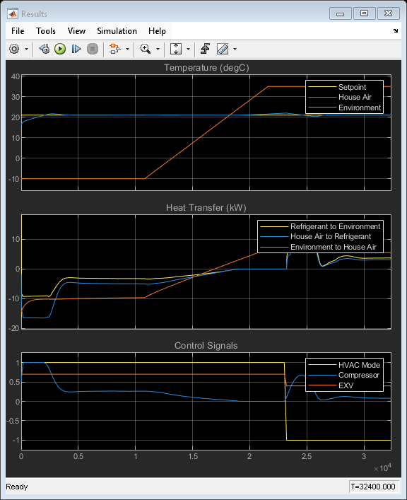
Simulation Results from Scopes
The scope shows temperatures, rates of heat transfer, and control signals in the model. The compressor is initially at 100% because the house starts in a cold state at 16 degC. The compressor ramps down once the house reaches the setpoint temperature, eventually shutting down when the environment is warm enough. After switching to air conditioning mode, the compressor ramps up to bring the house temperature back to the setpoint temperature before settling down again.
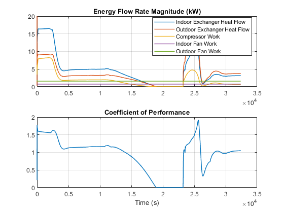
Simulation Results from Simscape Logging
This plot shows the heat transfer in the indoor and outdoor heat exchangers as well as the power consumed by the compressor and fans. The coefficient of performance (COP) is the ratio of the indoor heat exchanger heat transfer to the total power consumed. The COP of this system is around 2 or less, which is low, because the system and the controls have not been fully optimized.
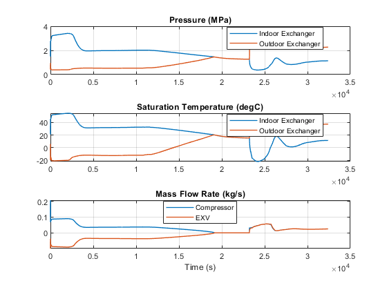
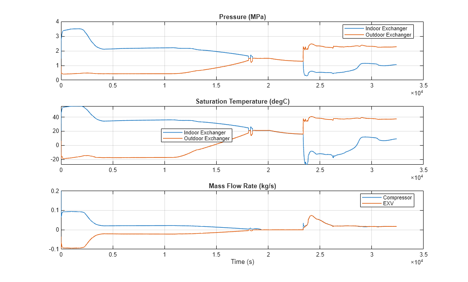
This plot shows the high and low pressures in the refrigeration cycle and the corresponding saturation temperatures. During heat pump mode, the directional valve directs refrigerant to the indoor heat exchanger first, so the electronic expansion valve flow rate and the compressor flow rate have opposite signs. During air conditioning mode, the direction valve switches the flow direction so that the electronic expansion valve flow rate and the compressor flow rate have the same sign.