Y-Junction (MA)
Libraries:
Simscape /
Fluids /
Moist Air /
Pipes & Fittings
Description
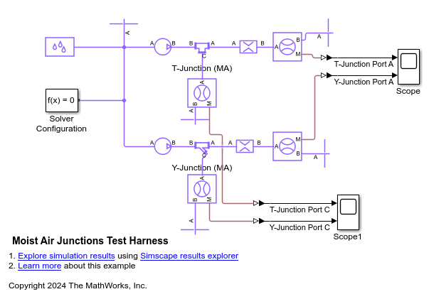
The Y-Junction (MA) block models a Y-junction consisting of a main branch and a side branch in a moist air network. The path between ports A and B is the main branch. The path between ports A and C or between ports B and C is the side branch. The side branch extends from the main branch at an angle specified by the value of the Junction angle between (A-C) parameter.
Flow Direction
The flow is converging when the flow through port C merges into the main flow. The flow is diverging when the branch flow splits from the main flow.
The block uses mode charts to determine each loss coefficient for a given flow
configuration. This
table
describes the conditions and coefficients when the Loss coefficient
model parameter is Custom.
| Flow Scenario | ṁA | ṁB | ṁC | KA | KB | KC |
|---|---|---|---|---|---|---|
| Stagnant | – | – | – | 1 or last valid value | 1 or last valid value | 1 or last valid value |
| Diverging from node A | >ṁthresh | <-ṁthresh | <-ṁthresh | 0 | Kmain,div | Kside,div |
| Diverging from node B | <-ṁthresh | >ṁthresh | <-ṁthresh | Kmain,div | 0 | Kside,div |
| Converging to node A | <-ṁthresh | >ṁthresh | >ṁthresh | 0 | Kmain,conv | Kside,conv |
| Converging to node B | >ṁthresh | <-ṁthresh | >ṁthresh | Kmain,conv | 0 | Kside,conv |
| Converging to node C (branch) | >ṁthresh | >ṁthresh | <-ṁthresh | (Kmain,conv + Kside,conv)/2 | (Kmain,conv + Kside,conv)/2 | 0 |
| Diverging from node C (branch) | <-ṁthresh | <-ṁthresh | >ṁthresh | (Kmain,div + Kside,div)/2 | (Kmain,div + Kside,div)/2 | 0 |
This table describes the conditions and coefficients when the Loss coefficient
model parameter is Idel'chik correlation.
| Flow Scenario | ṁA | ṁB | ṁC | KA | KB | KC |
|---|---|---|---|---|---|---|
| Stagnant | – | – | – | 1 or last valid value | 1 or last valid value | 1 or last valid value |
| Diverging from node A — Invalid | >ṁthresh | <-ṁthresh | <-ṁthresh | 0 | 1 | 1 |
| Diverging from node B | <-ṁthresh | >ṁthresh | <-ṁthresh | Kmain,div | 0 | Kside,div |
| Converging to node A — Invalid | <-ṁthresh | >ṁthresh | >ṁthresh | 0 | 1 | 1 |
| Converging to node B | >ṁthresh | <-ṁthresh | >ṁthresh | Kmain,conv | 0 | Kside,conv |
| Converging to node C (branch) — Invalid | >ṁthresh | >ṁthresh | <-ṁthresh | 1 | 1 | 0 |
| Diverging from node C (branch) — Invalid | <-ṁthresh | <-ṁthresh | >ṁthresh | 1 | 1 | 0 |
In stagnant flow, the mass flow rate conditions do not match any defined flow scenario. Stagnant flow is permitted at the start of the simulation, but the block does not revert to stagnant flow after it has achieved another mode. The mass flow rate threshold, which is the point at which the flow in the pipe begins to reverse direction, is
where:
Rec is the Critical Reynolds number parameter, beyond which the transitional flow regime begins.
ν is the fluid viscosity.
is the average fluid density.
Amin is the smallest cross-sectional area in the pipe junction.
Idel'chik Correlation Coefficient Model
When you set the Loss coefficient model parameter to
Idel'chik correlation, the block calculates the pipe loss
coefficients according to [2].
The block supports two flow configurations between the main branch from ports A and B and the side branch from port C. The side branch is offset from the main branch at an angle α, which is the value of the Junction angle between (A-C) parameter.
In a converging flow, the flow enters at ports A and C and exits at port B.

In a diverging flow, the flow enters at port B and exits at ports A and C.

You can control the block behavior in a prohibited flow configuration by using the
Report when flow configuration is invalid parameter. If the
Report when flow configuration is invalid parameter is set to
None or Warning, the model
continues to run in the prohibited flow configuration, but the results may not be
correct.
For a converging flow, the block calculates the loss coefficient of the side branch between ports C and B using a simplified version of Idel'chik that assumes the area of the main branch is constant. The loss coefficient of the side branch is
where:
are the mass flow rates from rates at ports A, B, and C, respectively.
AA, AB, AC are fitting coefficients for ports A, B, and C, respectively.
The block calculates the loss coefficient of the main branch between ports A and B using a simplified version of Idel'chik that assumes the main branch area is constant and , where Q is the volumetric flow rate through the specified port. The main branch loss coefficient is
For a diverging flow, the block calculates the loss coefficient of the side branch between ports C and B as
where
and
The block calculates the loss coefficient of the main branch between ports A and B as
Custom Y-Junction
When you set the Loss coefficient model parameter to
Custom, the block calculates the pipe loss coefficient at each
port, K, based on the user-defined loss parameters for converging and
diverging flow and mass flow rate at each port. You must specify
Kmain,conv,
Kmain,div,
Kside,conv, and
Kside,div as the Main branch
converging loss coefficient, Main branch diverging loss
coefficient, Side branch converging loss coefficient, and
Side branch diverging loss coefficient parameters, respectively. The
custom loss coefficient model behavior for the Y-junction is the same as for the custom
T-junction.
Mass and Momentum Balance
The block conserves mass in the junction such that
ṁi is the mixture mass flow rate for a given port, i.
wi is the water vapor mass flow rate for a given port, i.
gi is the trace gas mass flow rate for a given port, i.
di is the water droplet mass flow rate for a given port, i.
Flow through the pipe junction behaves according to the momentum conservation equations between ports A, B, and C:
where I represents the fluid inertia, and
Amain is the Main branch area (A-B) parameter and Aside is the Side branch area (C) parameter.
Energy Balance
The block balances energy such that
where:
ϕA is the energy flow rate at port A.
ϕB is the energy flow rate at port B.
ϕC is the energy flow rate at port C.
Variables
To set the priority and initial target values for the block variables prior to simulation, use the Initial Targets section in the block dialog box or Property Inspector. For more information, see Set Priority and Initial Target for Block Variables.
Nominal values provide a way to specify the expected magnitude of a variable in a model. Using system scaling based on nominal values increases the simulation robustness. Nominal values can come from different sources, one of which is the Nominal Values section in the block dialog box or Property Inspector. For more information, see Modify Nominal Values for a Block Variable.
Examples
Ports
Conserving
Parameters
References
[1] Idel’chik, I. E. Handbook of hydraulic resistance: Coefficients of local resistance and of friction. Jerusalem: Israel Program for Scientific Translations, 1966.
Extended Capabilities
Version History
Introduced in R2024b


