Pressure Reducing Valve (MA)
Libraries:
Simscape /
Fluids /
Moist Air /
Valves & Orifices /
Pressure Control Valves
Description
The Pressure-Reducing Valve (MA) block models a pressure-controlling reducing valve in a
moist air network. The valve is open when the pressure at port B is
less than the set pressure, and closes when the pressure exceeds that value. The control
pressure can be a constant, or, when you set Set pressure control
to Controlled, the set pressure can vary according to the
input signal at port Ps. For pressure control based on another
location in the fluid network, see the Pressure Compensator
Valve (MA) block.
Pressure Control
The valve closes when the pressure in the valve, pcontrol, exceeds the set pressure, pset. The valve is fully closed when the control pressure reaches pset + prange, where prange is the value of the Pressure regulation range parameter.
For the linear parametrizations, the block calculates the opening fraction of the
valve, λ. When you set Set pressure control
to Constant, λ is
where:
fleak is the value of the Leakage flow fraction parameter.
pcontrol is the control pressure, which is the difference between the pressure at port B and atmospheric pressure.
pset is the value of the Set pressure (gauge) parameter.
When you set Set pressure control to
Controlled, the valve opening fraction is
where ps is the value of the signal at port Ps. If the control pressure exceeds the valve pressure range, the valve opening fraction is fleak.
Momentum Balance
The flow rate in the valve depends on the Opening characteristic parameter:
Linear— The block scales the measure of flow capacity by λ to account for the valve opening area.Tabulated— The block interpolates the measure of flow capacity from either the Cv flow coefficient vector, Kv flow coefficient vector, Orifice area vector, or Sonic conductance vector parameters. This function uses a one-dimensional lookup table.
When you set Valve parametrization to Cv
flow coefficient, the mass flow rate is
where:
Cv is the flow coefficient.
N6 is a constant equal to 27.3 when mass flow rate is in kg/hr, pressure is in bar, and density is in kg/m3.
Y is the expansion factor.
pin is the inlet pressure.
pout is the outlet pressure.
vin is the inlet specific volume.
The expansion factor is
where:
Fγ is the ratio of the isentropic exponent to 1.4.
xT is the value of the xT pressure differential ratio factor at choked flow parameter.
The block smoothly transitions to a linearized form of the equation when the pressure ratio, , rises above the value of the Laminar flow pressure ratio parameter, Blam,
where:
When the pressure ratio, , falls below , the valve becomes choked and the block uses the equation
When you set Valve parametrization to Kv
flow coefficient, the block uses the same equations as the
Cv flow coefficient parametrization, but replaces
Cv with
Kv using the relation .
When you set Valve parametrization to
Orifice area, the mass flow rate is
where:
Cd is the value of the Discharge coefficient parameter.
γ is the isentropic exponent.
The block smoothly transitions to a linearized form of the equation when the pressure ratio, , rises above the value of the Laminar flow pressure ratio parameter, Blam,
When the pressure ratio, , falls below , the valve becomes choked and the block uses the equation
When you set Valve parametrization to Sonic
conductance, the mass flow rate is
where:
C is the sonic conductance.
Bcrit is the critical pressure ratio.
m is the value of the Subsonic index parameter.
Tref is the value of the ISO reference temperature parameter.
ρref is the value of the ISO reference density parameter.
Tin is the inlet temperature.
The block smoothly transitions to a linearized form of the equation when the pressure ratio, , rises above the value of the Laminar flow pressure ratio parameter Blam,
When the pressure ratio, , falls below the critical pressure ratio, Bcrit, the orifice becomes choked and the block switches to the equation
The Sonic conductance setting of the
Valve parameterization parameter is for pneumatic
applications. If you use this setting for moist air with high levels of trace
gasses or are modeling a fluid other than air, you may need to scale the sonic
conductance by the square root of the mixture specific gravity.
Mass Balance
The block conserves mass through the valve
where ṁ is the mass flow rate and the subscript w denotes water vapor, the subscript g denotes trace gas, and the subscript d denotes water droplets.
Opening Dynamics
When you select Opening dynamics, the block applies a first-order filter to the valve area based on the Opening time constant parameter, τ. The valve area, Avalve, becomes the dynamic area, Adyn,
When you select Opening dynamics, the valve does not respond to changes instantaneously. This figure shows an example valve area in response to a step in the valve input pressure with and without opening dynamics:
When you clear Opening dynamics, the valve area mirrors the step change in the pressure at the input.
When you select Opening dynamics and set Opening time constant to
0.1 s, the valve area asymptotically approaches its limit.
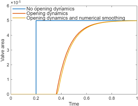
Specifying a nonzero value for the Smoothing factor parameter provides additional numerical stability when the valve area is changing and in the near-closed or near-open position. For more information, see Numerical Smoothing.
Energy Balance
Energy is conserved in the valve,
where:
ΦA is the energy flow at port A.
ΦB is the energy flow at port B.
Assumptions and Limitations
There is no heat exchange between the valve and the environment.
Ports
Conserving
Input
Parameters
References
[1] ISO 6358-3. "Pneumatic fluid power – Determination of flow-rate characteristics of components using compressible fluids – Part 3: Method for calculating steady-state flow rate characteristics of systems". 2014.
[2] IEC 60534-2-3. "Industrial-process control valves – Part 2-3: Flow capacity – Test procedures". 2015.
[3] ANSI/ISA-75.01.01. "Industrial-Process Control Valves – Part 2-1: Flow capacity – Sizing equations for fluid flow underinstalled conditions". 2012.
[4] P. Beater. Pneumatic Drives. Springer-Verlag Berlin Heidelberg. 2007.