Using ForEach Subsystems in HDL Coder
This example shows how you can use a For Each Subsystem to implement a streaming square root algorithm by cascading identical CORDIC iterations. You can then generate code for the algorithm by using HDL Coder™.
Using CORDIC Algorithm for Hardware Functions
CORDIC is an iterative algorithm that can be used to approximate fixed-point mathematics such as trigonometric functions, square root, and divide. The iterative core is composed of simple shift and add operations, allowing the algorithm to be implemented efficiently on FPGA or ASIC hardware. For low data rate applications, a single core can be reused to perform all iterations and achieve a very small area footprint. For applications requiring a new data sample to be processed at each clock cycle, a separate core can be used to calculate each iteration in a cascaded chain, as shown in the following diagram.
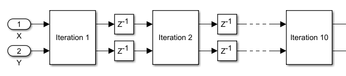
While it is straightforward to manually cascade the cores in Simulink®, the ability to automatically adjust the number of cores based on a parameter value would be highly desirable. You can do exactly that using a For Each Subsystem.
Cascade CORDIC Iterations Using For Each Subsystem
In this model, the iterative core is placed into a For Each Subsystem to be repeated N times, where N is the number of iterations defined in the upper-level block mask. The N core outputs form a vector at the For Each Subsystem output, where they are pipelined, and then fed back into the For Each Subsystem inputs. Outputs from core (1:N-1) are connected to inputs of core (2:N), exactly the same as in the manually cascaded model.
A valid signal path is included to handle intermittent input data, and tested by inserting random gaps between valid data samples.
open_system('hdlcoder_foreach_cordic')
open_system('hdlcoder_foreach_cordic/For Each Cordic Sqrt','force')

Compare Output to CORDIC Square Root Reference
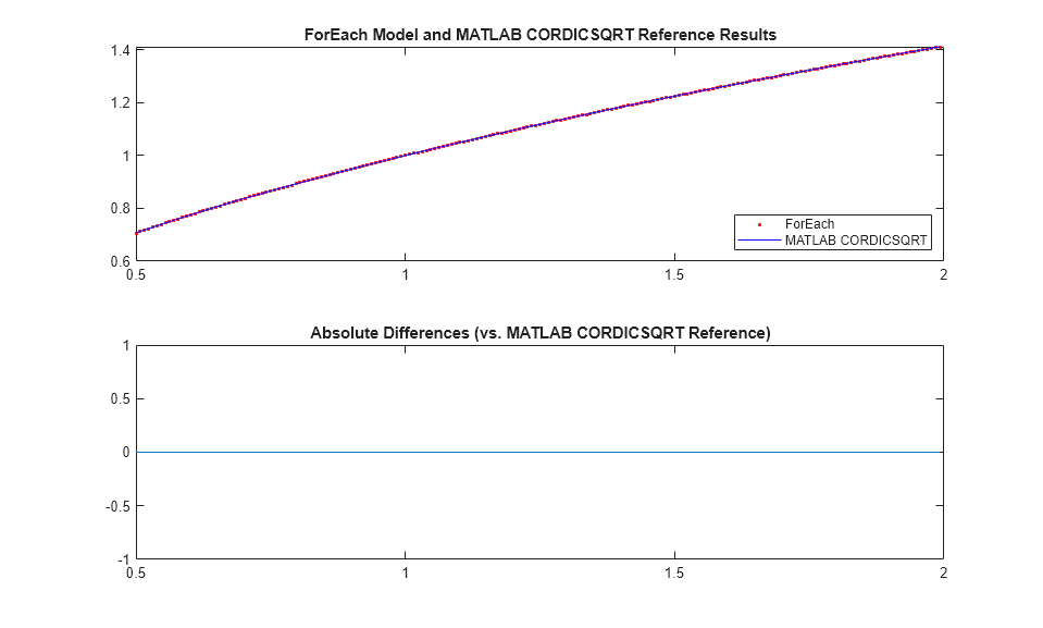
Using a 14-bit signed input in the range of [0.5,2), the output of the Simulink model matches the cordicsqrt reference function exactly. Input range outside of [0.5,2) is not expected to work because the example lacks a normalizer stage.
In addition, the final gain adjustment in the model uses an 18-bit gain parameter for optimal FPGA DSP mapping; while the cordicsqrt function matches the gain parameter word length to that of the gain input. This results in slight differences between the Simulink model output and the cordicsqrt function when other input data types are used.
slout = sim('hdlcoder_foreach_cordic');
data_out = slout.logsout.getElement('data out').Values.Data;
valid_out = slout.logsout.getElement('valid out').Values.Data;
data_out = data_out(valid_out);

ref_cordic = double(cordicsqrt(v_fix, niter));
data_in = double(v_fix);
data_out = double(data_out');

figure;
subplot(211);
plot(data_in, data_out, 'r.', data_in, ref_cordic, 'b-');
legend('ForEach', 'MATLAB CORDICSQRT', 'Location', 'SouthEast');
title('ForEach Model and MATLAB CORDICSQRT Reference Results');
subplot(212);
absErr = abs(ref_cordic - data_out);
plot(data_in, absErr);
title('Absolute Differences (vs. MATLAB CORDICSQRT Reference)');
Generate HDL Code
makehdl('hdlcoder_foreach_cordic/For Each Cordic Sqrt');
### Working on the model <a href="matlab:open_system('hdlcoder_foreach_cordic')">hdlcoder_foreach_cordic</a>
### Generating HDL for <a href="matlab:open_system('hdlcoder_foreach_cordic/For Each Cordic Sqrt')">hdlcoder_foreach_cordic/For Each Cordic Sqrt</a>
### Using the config set for model <a href="matlab:configset.showParameterGroup('hdlcoder_foreach_cordic', { 'HDL Code Generation' } )">hdlcoder_foreach_cordic</a> for HDL code generation parameters.
### Running HDL checks on the model 'hdlcoder_foreach_cordic'.
### Begin compilation of the model 'hdlcoder_foreach_cordic'...
### Begin compilation of the model 'hdlcoder_foreach_cordic'...
### Working on the model 'hdlcoder_foreach_cordic'...
### Working on... <a href="matlab:configset.internal.open('hdlcoder_foreach_cordic', 'GenerateModel')">GenerateModel</a>
### Begin model generation 'gm_hdlcoder_foreach_cordic'...
### Copying DUT to the generated model....
### Model generation complete.
### Generated model saved at <a href="matlab:open_system('hdlsrc/hdlcoder_foreach_cordic/gm_hdlcoder_foreach_cordic.slx')">hdlsrc/hdlcoder_foreach_cordic/gm_hdlcoder_foreach_cordic.slx</a>
### Begin VHDL Code Generation for 'hdlcoder_foreach_cordic'.
### Unused logic removed during HDL code generation. To highlight the logic removed, click the following MATLAB script: hdlsrc/hdlcoder_foreach_cordic/highlightRemovedDeadBlocks.m
### To clear highlighting, click the following MATLAB script: hdlsrc/hdlcoder_foreach_cordic/clearHighlightingRemovedDeadBlocks.m
### Working on hdlcoder_foreach_cordic/For Each Cordic Sqrt/MATLAB Function2 as hdlsrc/hdlcoder_foreach_cordic/MATLAB_Function2.vhd.
### Working on hdlcoder_foreach_cordic/For Each Cordic Sqrt/For Each Subsystem/MATLAB Function1 as hdlsrc/hdlcoder_foreach_cordic/MATLAB_Function1.vhd.
### Working on hdlcoder_foreach_cordic/For Each Cordic Sqrt/For Each Subsystem as hdlsrc/hdlcoder_foreach_cordic/For_Each_Subsystem.vhd.
### Working on hdlcoder_foreach_cordic/For Each Cordic Sqrt as hdlsrc/hdlcoder_foreach_cordic/For_Each_Cordic_Sqrt.vhd.
### Generating package file hdlsrc/hdlcoder_foreach_cordic/For_Each_Cordic_Sqrt_pkg.vhd.
### Code Generation for 'hdlcoder_foreach_cordic' completed.
### Generating HTML files for code generation report at <a href="matlab:hdlcoder.report.openReportV2Dialog('/tmp/Bdoc26a_3233028_1590811/tp28802261/hdlcoder-ex98135077/hdlsrc/hdlcoder_foreach_cordic', '/tmp/Bdoc26a_3233028_1590811/tp28802261/hdlcoder-ex98135077/hdlsrc/hdlcoder_foreach_cordic/html/index.html')">index.html</a>
### Creating HDL Code Generation Check Report file:///tmp/Bdoc26a_3233028_1590811/tp28802261/hdlcoder-ex98135077/hdlsrc/hdlcoder_foreach_cordic/For_Each_Cordic_Sqrt_report.html
### HDL check for 'hdlcoder_foreach_cordic' complete with 0 errors, 0 warnings, and 1 messages.
### HDL code generation complete.
Additional Modeling Guidelines
Observe the following guidelines when cascading blocks in your algorithm using For Each Subsystem:
Since For Each Subsystem is atomic, the connection between output of block X and input of block X+1 creates an artificial algebraic loop. To break this loop, place pipeline registers between cascading blocks outside of the For Each Subsystem, as demonstrated in this example.
A mux block is used to concatenate external input and outputs of block
(1:N-1)to form the inputs of the For Each Subsystem. This requires the cascading blocks to use the same input and output data types.