Model Design for AXI4-Stream Video Interface Generation
For designs that require high speed video streaming use AXI4-Stream Video interfaces. Choose from these two modeling styles based on how your algorithm operates:
Sample-Based Modeling — Use these guidelines when your algorithm operates on a stream of samples.
Frame-Based Modeling — Use these guidelines when your algorithm operates on a complete frame of data. The data signals at the design under test (DUT) boundary must be matrices. Do not use this mode if you want to model the streaming pixel protocol.
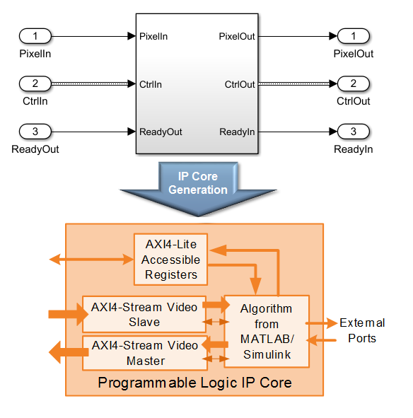
With the HDL Coder™ software, you can implement a simplified, streaming pixel protocol in your model. The software generates an HDL IP core with AXI4-Stream Video interfaces.
Sample Based Modeling
With the HDL Coder software, you can implement a simplified, streaming pixel protocol in your model. The software generates an HDL IP core with AXI4-Stream Video interfaces. You can use the streaming pixel protocol for AXI4-Stream Video interface mapping. Video algorithms process data serially and generate video data as a serial stream of pixel data and control signals. To learn about the streaming pixel protocol, see Streaming Pixel Interface (Vision HDL Toolbox).
To generate an IP core with AXI4-Stream Video interfaces, in your DUT interface, implement these signals:
Pixel Data
Pixel Control Bus
The Pixel Control Bus is a bus that has these signals:
hStarthEndvStartvEndvalid
The signals hStart and hEnd represent the start of an active line and the end of an active line respectively. The signals vStart and vEnd represent the start of a frame and the end of a frame.
You can optionally model the backpressure signal, Ready, and map it to the AXI4-Stream Video interface.
Protocol Signals and Timing Diagrams
This figure is a 2-by-3 pixel image. The active image area is the rectangle with a dashed line around it and the inactive pixels that surround it. The pixels are labeled with their grayscale values.
![]()
Pixel Data and Pixel Control Bus
This figure shows the timing diagram for the Pixel Data and Pixel Control Bus signals that you model at the DUT interface.

The Pixel Data signal is the primary video signal that is transferred across the AXI4-Stream Video interface. When the Pixel Data signal is valid, the valid signal is asserted.
The hStart signal becomes high at the start of the active lines. The hEnd signal becomes high at the end of the active lines.
The vStart signal becomes high at the start of the active frame in the second line. The vEnd signal becomes high at the end of the active frame in the third line.
Optional Ready Signal
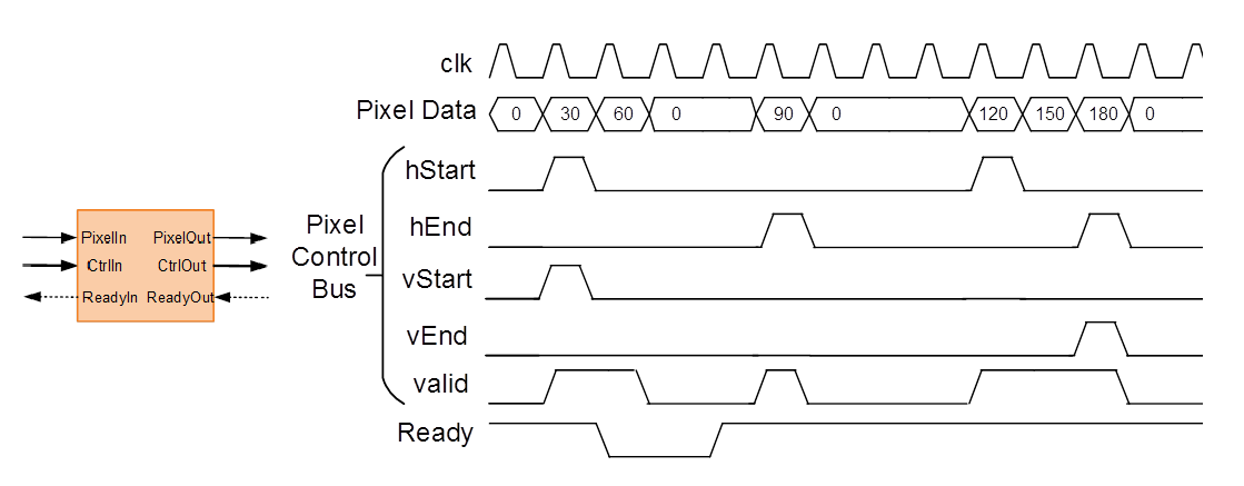
This figure shows the timing diagram for the Pixel Data, the Pixel Control Bus, and the Ready signal that you model at the DUT interface.

When you map the DUT ports to an AXI4-Stream Video interface, you can optionally model the backpressure signal, Ready, and map it to the AXI4-Stream Video interface.
In a Slave interface, with the Ready signal, you can apply back pressure. In a Master interface, with the Ready signal, you can respond to back pressure.
If you model the Ready signal in your AXI4-Stream Video interfaces, your Master interface must deassert its valid signal one cycle after the Ready signal is deasserted.
If you do not model the Ready signal, HDL Coder generates the associated backpressure logic.
Model Data and Control Bus Signals
You can model your video algorithm with Pixel Data and Pixel Control Bus signals at the DUT ports and map the signals to AXI4-Stream Video interfaces. You can optionally model the backpressure signal, Ready, and map it to the AXI4-Stream Video interface.

This figure shows an example of a top-level Simulink® model with a Video Source input.

The Frame To Pixels and Pixels To Frame blocks perform the conversion between the video frames and the Pixel Data and Pixel Control Bus at the DUT interface. To use these blocks, you must have the Vision HDL Toolbox™ installed.
See also Frame To Pixels (Vision HDL Toolbox) and Pixels To Frame (Vision HDL Toolbox).
Pixel Data and Pixel Control Bus Modeling
This figure shows how to model the Pixel Data and Pixel Control Bus signals inside the DUT subsystem.

You can directly connect the valid signal from the Pixel Control Bus to the Enable port. If you do not have the Vision HDL Toolbox software, replace the Pixel Control Bus Selector and Pixel Control Bus Creator blocks with the Bus Selector and Bus Creator blocks respectively.
Ready Signal Modeling
The AXI4-Stream Video interfaces in your DUT can optionally include a Ready signal.
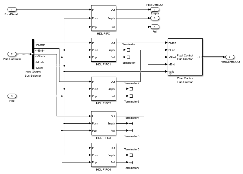
For example, you can have a FIFO in your DUT to store some video data before processing the signals. Use a FIFO Subsystem that contains HDL FIFO blocks to store the Pixel Data and the Pixel Control Bus signals. To apply the backpressure to the upstream component, model the Ready signal based on the FIFO Full signal.
This figure shows how to model the Ready signal inside the DUT subsystem.

The FIFO Subsystem block uses HDL FIFO blocks for the Pixel Data and for the Pixel Control Bus signals.

Disable delay balancing for the Ready signal path. If you enable delay balancing, the code generator can insert one or more delays on the Ready signal.
Map DUT Ports to Multiple Channels
When you run the IP Core Generation workflow, you can map multiple
DUT ports to AXI4-Stream Video Master and AXI4-Stream Video
Slave channels. The DUT ports mapped to multiple interface
channels must use scalar data type. When you use vector ports, you can map the ports to
at most one AXI4-Stream Video Master channel and one
AXI4-Stream Video Slave channel.
To learn more, see Generate HDL IP Core with Multiple AXI4-Stream and AXI4 Master Interfaces.
Model Designs with Multiple Sample Rates
The HDL Coder software supports designs with multiple sample rates when you run the IP Core Generation workflow. When you map the interface ports to AXI4-Stream Video Master or AXI4-Stream Video Slave interfaces, to use multiple sample rates, ensure that the DUT ports that map to these AXI4 interfaces run at the fastest rate of the design after HDL code generation.
To learn more, see Generate IP Core from Multirate Model.
Video Porch Insertion Logic
Video capture systems scan video signals from left to right and from top to bottom. As these systems scan, they generate inactive intervals between lines and frames of active video. This inactive interval is called a video porch. The horizontal porch consists of inactive cycles between the end of one line and the beginning of next line. The vertical porch consists of inactive cycles between the ending active line of one frame and the starting active line of next frame.
This figure shows a video frame with the horizontal porch split into a front and a back porch.
![]()
The AXI4-Stream Video interface does not require a video porch, but Vision HDL Toolbox algorithms require a porch for processing video streams. If the incoming pixel stream does not have a sufficient porch, HDL Coder inserts the required amount of porch to the pixel stream. By using the AXI4-Lite registers in the generated IP core, you can customize these porch parameters for each video frame:
Active pixels per line (Default: 1920)
Active video lines: (Default: 1080)
Horizontal porch length (Default: 280)
Vertical porch length (Default: 45)
Default Video System Reference Design
You can integrate the generated HDL IP core with AXI4-Stream Video interfaces into the
Default video system reference design.
This figure is a block diagram of the Default video system
reference design architecture.

You can use this Default video system reference design
architecture with these target platforms:
Xilinx Zynq ZC702 evaluation kitXilinx Zynq ZC706 evaluation kitZedBoard
To use the Default video system reference design, you must
install the Support Package for SoC Blockset™ Support Package for AMD FPGA and SoC Devices.
Restrictions
When you map the DUT ports to AXI4-Stream Video interfaces:
The DUT port mapped to the Pixel Data signal must use a scalar data type.
Xilinx® Zynq®-7000 must be your target platform.
You must use Xilinx Vivado® as your synthesis tool.
Processor/FPGA synchronization must be
Free running.
Frame-Based Modeling
Model your DUT algorithm to operate on frames of data and map your matrix port to an AXI4-Stream Video interface by using the frame-to-sample optimization. For more information, see Model Design for Frame-Based IP Core Generation.
See Also
Topics
- Model Design for AXI4-Stream Interface Generation
- Streaming Pixel Interface (Vision HDL Toolbox)