Generate HDL IP Core for Frame-Based MATLAB Function with AXI4-Stream Interfaces
R2026bThis example shows how to generate a sample-based HDL IP core that has AXI4-Stream interfaces from a frame-based MATLAB® function by using the frame-to-sample optimization. Deploy the IP core to a ZedBoard and verify the IP core by using MATLAB and live streaming data.
It is natural to express many algorithms in MATLAB by using frame operations that work on entire matrices. These algorithms are also well-suited for FPGAs, which can efficiently process large amounts of data. However, when deployed to an FPGA, data typically arrives as a stream of samples rather than as complete frames. To enable efficient deployment in this context, frame-based algorithms must be converted to a sample-based streaming implementation. HDL Coder™ transforms frame-based algorithms into a sample-based streaming architecture by using the frame-to-sample optimization and generates the required valid and ready control signals. For details on how to model designs for frame-based code generation, see HDL Code Generation from Frame-Based Algorithms.
In this example, you:
Design a 2-D Constant False Alarm Rate (CFAR) detector by using the
hdl.npufunfunction.Verify the floating-point implementation against the
phased.CFARDetector2DSystem object™ from the Phased Array System Toolbox™.Convert the floating-point algorithm implementation to fixed point.
Generate an HDL IP core that has AXI4-Stream interfaces by using the MATLAB HDL Workflow Advisor.
Deploy the IP core to a ZedBoard and verify with live FPGA data against both the fixed-point DUT and the
phased.CFARDetector2DSystem object behavioral reference.
Prerequisites
To run this example, you need these products:
For code generation:
HDL Coder
Phased Array System Toolbox (for the golden reference used in the testbench)
For deployment:
SoC Blockset™ (for AMD®)
SoC Blockset Support Package for AMD FPGA and SoC Devices (for deployment)
Xilinx Vivado® (For supported versions, see HDL Language Support and Supported Third-Party Tools and Hardware)
ZedBoard. For setup instructions, see the "Set Up Zynq Hardware and Tools" section in Get Started with IP Core Generation from Simulink Model.
Model a CFAR Algorithm Using Neighborhood Processing Functions
Radar systems can detect targets by analyzing a range-Doppler map where each matrix element represents a combination of distance and velocity. Targets appear as peaks in the matrix while the remaining matrix elements contain noise that varies across it. CFAR is a common radar technique to detect such targets. It works by setting a detection threshold for each cell based on an estimate of the surrounding noise level to decide which cells contain actual targets. There are multiple strategies to estimate the noise. In this example, the design uses the Cell-Averaging (CA) strategy, which averages the power in a neighborhood of training cells around the cell under test (CUT) to estimate the noise, then scales this estimate by a threshold factor to set the detection threshold.
Implementing CFAR detection in real time requires processing every cell in the range-Doppler map at the radar update rate, which makes it well suited for FPGA acceleration. On a Zynq SoC, the radar signal processing chain from digitized samples to detected targets can be partitioned into modular IP cores connected via AXI4-Stream in the FPGA programmable logic, while the ARM processor handles higher-level tasks, such as target tracking and parameter tuning. In this example, you implement the CFAR stage as a standalone HDL IP core that processes a 2-D matrix representing the range-Doppler map. Open the mlhdlc_ip_cfar2d function to examine the frame-based CFAR detector design.
open mlhdlc_ip_cfar2d.mThe mlhdlc_ip_cfar2d function implements a 2-D CA-CFAR detector that processes a 64-by-128 range-Doppler map by using a 9-by-9 sliding window. The window consists of a 3-by-3 guard region surrounding the CUT and 72 training cells that estimate the local noise power, as shown in the following figure.
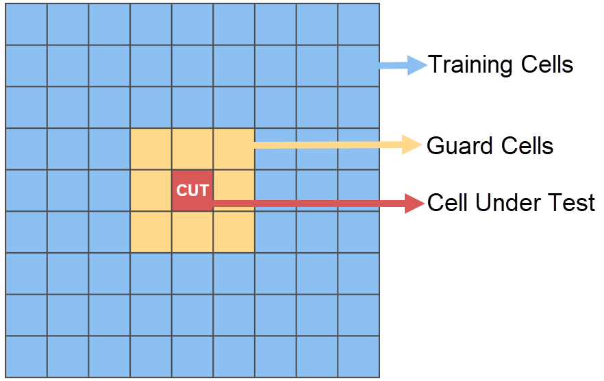
The red cell is the CUT, the orange cells form the 3-by-3 guard region, and the blue cells are the 72 training cells used to estimate the local noise power. The design calls the hdl.npufun function twice to perform neighborhood operations. The first call uses a 9-by-9 kernel defined by the cfarKernel function that computes the cell-averaging CFAR detection for every cell in the map. The second call uses a 1-by-1 kernel defined by the boundaryKernel function with the RowColumnInputs name-value argument set to true to suppress detections at boundary cells where the 9-by-9 window extends outside the range-Doppler map, that is, rows less than 5 or greater than 60 and columns less than 5 or greater than 124. This example splits the detection and boundary logic into separate neighborhood operations to show multiple kernel operations in the same DUT.
% CFAR detection: 9x9 sliding window
rawDetection = hdl.npufun(@cfarKernel, [9 9], rangeDopplerMap, ...
    "KernelArg", thresholdFactor);

% Boundary suppression: pass through interior cells, suppress boundaries
detectionMap = hdl.npufun(@boundaryKernel, [1 1], rawDetection, ...
    RowColumnInputs=true);
Review the Testbench
Open the mlhdlc_ip_cfar2d_tb testbench to examine the verification approach.
open mlhdlc_ip_cfar2d_tb.mThe threshold factor used in the testbench is set to K = 8. This value is derived from the CA-CFAR false alarm probability formula for square-law detected noise with N training cells:
With training cells, solving for an operating point of this gives:
This value balances false alarm suppression against detection sensitivity.
In this example, the behavior of the hdl.npufun function 2-D CFAR implementation is verified against the phased.CFARDetector2D (Phased Array System Toolbox) System object™ from the Phased Array System Toolbox, which provides the floating-point behavioral reference. The reference detector is configured to match the parameters used in mlhdlc_ip_cfar2d. The GuardBandSize property is set to [1 1] and the TrainingBandSize property is set to [3 3] to produce the same 9×9 window with 72 training cells. The CustomThresholdFactor property is set to 8 to match the DUT threshold factor. The OutputFormat property is set to 'CUT result' so the reference also produces logical detection decisions. The System object evaluates interior cells only, which matches the behavior achieved through the boundary suppression performed by the DUT using the RowColumnInputs name-value argument.
cfarRef = phased.CFARDetector2D( ...
    'Method',                'CA', ...
    'GuardBandSize',         [1 1], ...
    'TrainingBandSize',      [3 3], ...
    'ThresholdFactor',       'Custom', ...
    'CustomThresholdFactor', K, ...
    'OutputFormat',          'CUT result');
The testbench generates complex Gaussian noise and applies square-law detection (abs(x).^2) to simulate what upstream FPGA pipeline stages produce (Range FFT → Doppler FFT → |x|²). Five targets are injected at known cells with amplitude A = 3.0. Both detectors process 100 trials independently and their results are compared on 64-by-128 maps. The DUT suppresses boundary cells by using the RowColumnInputs name-value argument and the phased.CFARDetector2D System object reference evaluates only interior cells, so boundary cells are false in both.
Run the testbench to compare the HDL DUT against the phased.CFARDetector2D System object behavioral reference across 100 different maps.
mlhdlc_ip_cfar2d_tb;
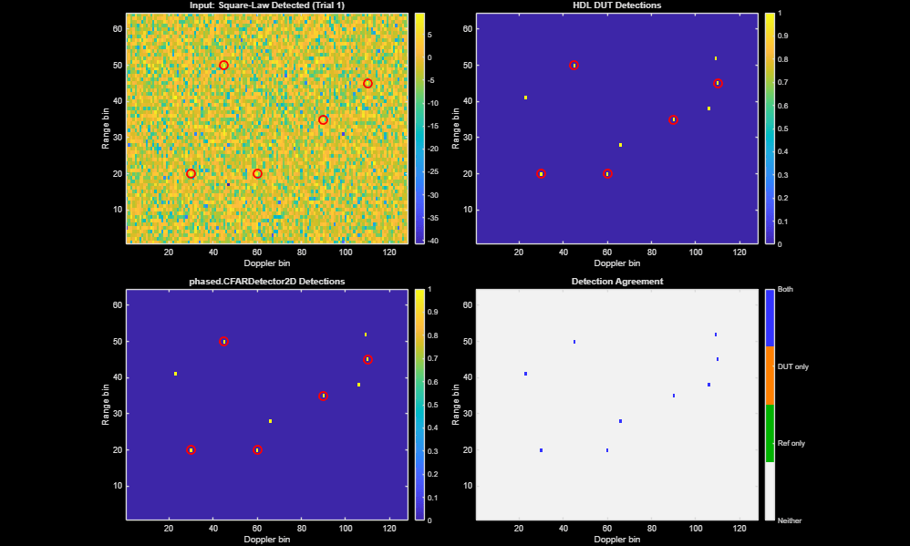
The mlhdlc_ip_cfar2d_tb testbench produces two figures and a summary table. The first figure shows a four-panel comparison for a single trial. The top-left panel displays the square-law detected range-Doppler map with target locations marked. The top-right panel shows the detection map produced by mlhdlc_ip_cfar2d. The bottom-left panel shows the detection map produced by the phased.CFARDetector2D System object. The bottom-right panel is an agreement map that indicates where both detectors agree (blue), where only the DUT detects (orange) and where only the reference detects (green). In the following trial, both the System object and the DUT implementation match, and all detections appear in blue.
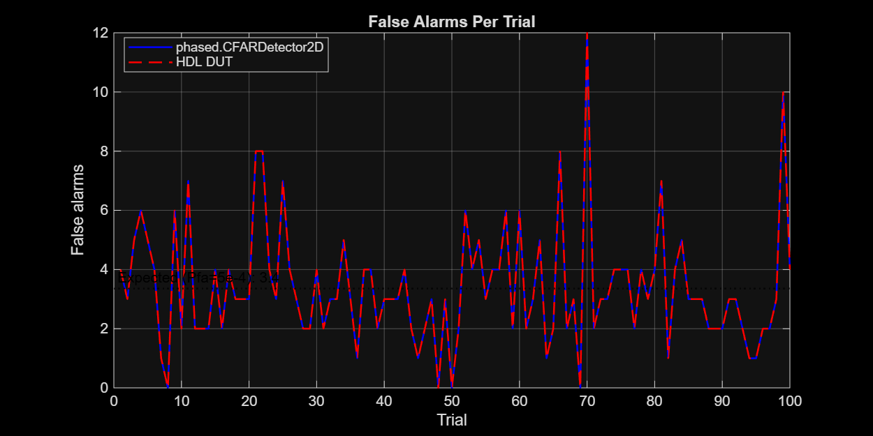
The second figure shows the number of false alarms per trial for both detectors. The DUT and reference detector produce identical results on all interior cells across all 100 trials, confirming that the hdl.npufun function implementation is functionally equivalent to the Phased Array System Toolbox behavioral model when using floating point.
Next, create and configure the MATLAB HDL Coder project to generate the HDL IP core.
Create MATLAB HDL Coder Project
Create an HDL Coder project by entering this command in the MATLAB Command Window.
coder -hdlcoder -new mlhdlc_ip_cfar2d_prj
Alternatively, in the Apps tab, click HDL Coder.
1. Set up the Xilinx Vivado synthesis tool path by using the hdlsetuptoolpath command in the MATLAB Command Window, and replace the path with your installation path.
hdlsetuptoolpath("ToolName", "Xilinx Vivado", "ToolPath", vivadopath);
2. In the HDL Workflow Advisor task, set Code Generation Workflow to MATLAB to HDL, and set Fixed-Point Conversion to Convert fixed-point at build time.
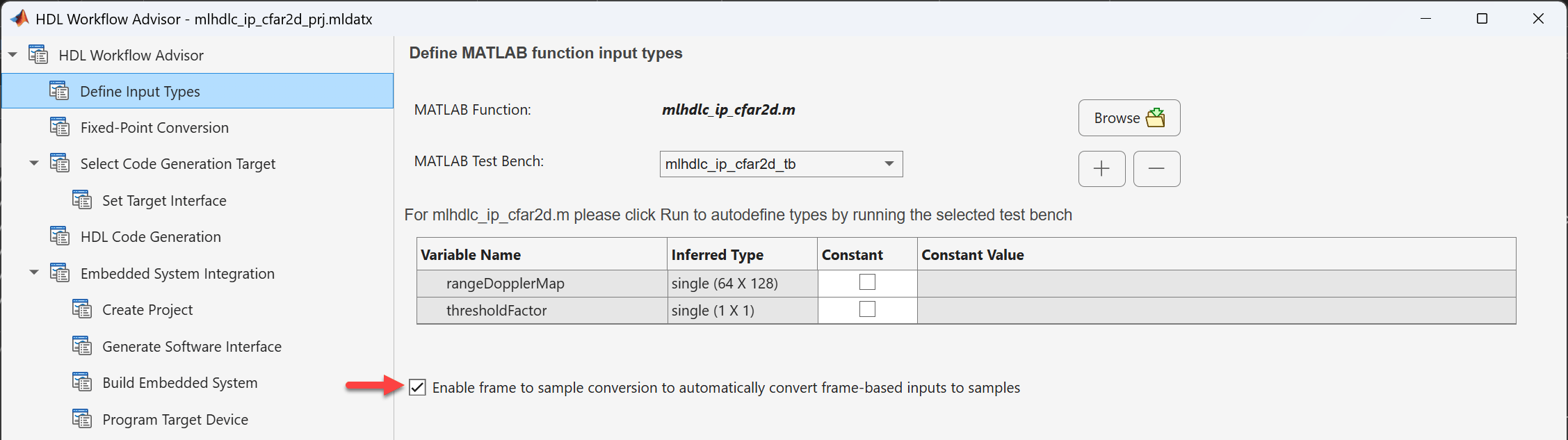
3. In the Define Input Types task, set the MATLAB Function to mlhdlc_ip_cfar2d and set the MATLAB Test Bench to mlhdlc_ip_cfar2d_tb. Select the Enable frame to sample conversion to automatically convert frame-based inputs to samples option to enable the frame-to-sample optimization.
4. Perform fixed-point conversion of the CFAR algorithm following the workflow in the Fixed-Point Conversion task:
Click Build in the toolstrip. When the build finishes, the Fixed-Point Conversion task shows a bottom pane with the inputs and outputs.
Use the fixed-point toolstrip actions to iterate on the proposed types for the inputs of the DUT.
To reproduce the results in this example, in the Variables tab, in the Proposed Type column, set the proposed type of the
rangeDopplerMapvariable tonumerictype(0, 14, 9), setthresholdFactortonumerictype(0, 4, 0), and setdetectionMapandrawDetectiontonumerictype(0, 1, 0).Click Validate Types and Test Numerics to verify the behavior of the fixed-point code.
Generate HDL IP Core
1. Configure the HDL Workflow Advisor to generate an IP core for a ZedBoard.
Set Workflow to
IP Core Generation.Set Platform to
ZedBoard.Set Synthesis tool to
Xilinx Vivado.Set Target Frequency (MHz) to
100.Under IP core settings, set Reference design to
Default system.
Click Validate Settings after you set all the parameters to build the target interface and continue to the next task.
2. In the Set Target Interface task, set the Target Platform Interface for the rangeDopplerMap port to AXI4 Stream Slave. Set the Target Platform Interface for the detectionMap port to AXI4 Stream Master. For both rangeDopplerMap and detectionMap, set the Bit Range to Data. Set the Target Platform Interface for the thresholdFactor port to AXI4 Lite so that HDL Coder generates an ARM-accessible register for runtime tuning. After all ports are set, the Set Target Interface task shows a green check mark and you can move to the next task.
3. In the HDL Code Generation task, in the Optimizations tab, enable Aggressive Dataflow Conversion and Distributed Pipeline Registers. Then set Pipeline distribution priority to Performance, and set Input Pipelining to 32 and Output Pipelining to 32. These optimizations allow HDL Coder to distribute registers across the implementation of the kernel operations and achieve timing closure at 100 MHz. Then click Run to generate the HDL IP core.
Integrate IP Core and Build
After generating the IP core, integrate it with the reference design, then synthesize and download the bitstream.
1. Under the Embedded System Integration task, right-click the Create Project subtask and select Run this Task. A Xilinx Vivado project is generated that integrates the CFAR IP core into the Default system reference design. Data flows from the ARM processing system through a DMA to the CFAR IP core.
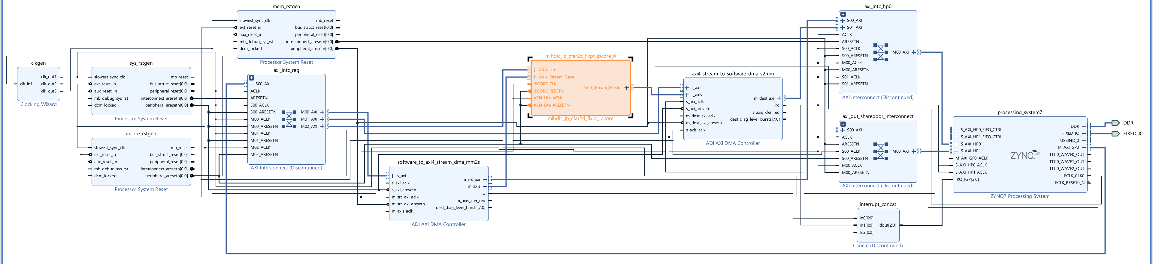
2. Click the Generate Software Interface subtask and verify that the Skip this step option is cleared. Then right-click Run. This generates two MATLAB files in your current folder: gs_mlhdlc_ip_cfar2d_fixpt_setup.m configures the fpga hardware object with the mapped ports and interfaces, and gs_mlhdlc_ip_cfar2d_fixpt_interface.m creates a connection to the FPGA for reading and writing data.
3. To generate the bitstream, go to the Build Embedded System subtask, select Run build process externally, then click Run. The Xilinx synthesis tool runs as a separate process outside of MATLAB. Wait for the synthesis tool to complete.
4. After generating the bitstream, go to the Program Target Device subtask and select Run This Task to program the ZedBoard.
Verify IP Core on ZedBoard Hardware
After programming the FPGA, verify the generated IP core by running the mlhdlc_ip_cfar2d_hw_verify script. This script generates 300 test frames by using a different random seed and target locations from the testbench used during code generation, then performs a comparison between the FPGA output, the fixed-point MATLAB DUT defined by the mlhdlc_ip_cfar2d_wrapper_fixpt_mex MEX file generated during the fixed-point conversion step for accelerated execution, and the phased.CFARDetector2D System object behavioral reference.
open mlhdlc_ip_cfar2d_hw_verify.mThe script connects to the ZedBoard by using the generated host interface script, writes the threshold factor once via AXI4-Lite, then loops over all 300 frames sending each range-Doppler map via AXI4-Stream and reading back the detection map:
% Connect to FPGA
hProcessor = xilinxsoc();
hFPGA = fpga(hProcessor);
gs_mlhdlc_ip_cfar2d_fixpt_setup(hFPGA);

% Write threshold factor (AXI4-Lite)
writePort(hFPGA, "thresholdFactor", K);

% Process frames through FPGA (AXI4-Stream)
for k = 1:ntrials
    writePort(hFPGA, "rangeDopplerMap", x2(:,:,k));
    fpgaDets(:,:,k) = readPort(hFPGA, "detectionMap");
end
The writePort function casts the input data to the DUT port data type automatically. The comparison operates on full 64-by-128 frames. Cell-by-cell agreement is computed for: FPGA vs fixed-point DUT, FPGA vs phased.CFARDetector2D, and fixed-point DUT vs phased.CFARDetector2D. Small differences between the fixed-point results and the floating-point phased.CFARDetector2D reference are expected due to data-type quantization.
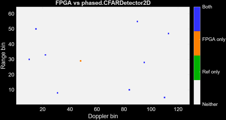
The script produces a six-panel figure for trial 110 showing the input, detection maps from all three sources and two agreement maps. The following figure shows the agreement map between the FPGA detections and the phased.CFARDetector2D System object detections, which indicates where both detectors agree (blue), where only the FPGA detects (orange), and where only the reference detects (green). In the following trial, both the System object and the DUT implementation match in most cells, and there is one cell that only the FPGA detects.
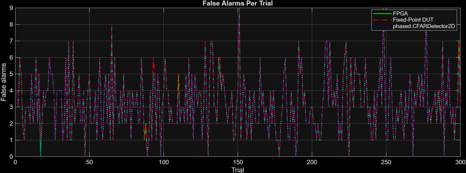
A second figure shows false alarm counts per trial for all three sources. The following figure shows the false alarm counts for the FPGA output, the fixed-point MATLAB DUT, and the phased.CFARDetector2D.
Additionally, the script prints a PASS/FAIL summary based on whether the FPGA output matches the fixed-point DUT on all cells across all 300 trials. The following summary shows the result for the data used in mlhdlc_ip_cfar2d_hw_verify. Each comparison shows the number of detections of each output and the percentage of agreement. The trial is considered passing if the agreement of the FPGA DUT and fixed-point implementation is higher than 99.999%.
============================================================
mlhdlc_ip_cfar2d: Three-Way Hardware Verification
300 trials, 64x128 maps, K=8
============================================================
FPGA vs phased.CFARDetector2D: 2457595 / 2457600 (99.9998%)
FPGA vs Fixed point DUT implementation: 2457596 / 2457600 (99.9998%)
Fixed-Point DUT vs Reference: 2457591 / 2457600 (99.9996%)
RESULT: PASSED (FPGA matches fixed-point DUT)
============================================================

