Define Trigger Properties
This example shows how to specify triggers. After you create faults and assign behaviors to them, you can specify how and when each fault is injected. Although you can select more than one fault for simulation, you can select only one active fault on each model element. See Define and Model Faults.
Video Walkthrough
For a walkthrough of the example, play the video.
Specify Fault Triggers
When you create faults, you can specify how and when they inject by specifying the trigger. When the trigger is true, the fault is injected. For more information on the triggers you can select, see Trigger type.
Open the sldemo_fuelsys_fault_analyzer model and set up the faults with the helper function, myFuelSysCase. The helper function deletes the existing Simulink® Fault Analyzer™ model artifacts and replaces them with the faults used in the example.
myFuelSysCase(3)
After executing the function, the model contains faults on each input signal of the To Controller subsystem. The throttle signal contains two faults and the other signals contain one fault. In this example, you define the trigger properties so the fault on the throttle signal named throttle_fault and the fault on the speed signal are injected after 25 seconds of simulation time.
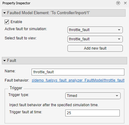
Click the fault badge on the throttle signal. In the throttle_fault preview window, click the Fault Operations button and click Properties.

The Property Inspector displays the properties. In the Trigger section, set the Trigger type property to Timed. Set the Trigger fault at time property to 25.
Repeat these steps for the fault on the speed signal. You can also create conditional triggers based on expressions or the values of model elements. For more information, see Create and Manage Conditionals.
Select Faults and Prepare for Simulation
After specifying the properties of the faults, you must select which faults are injected during simulation by enabling a model element that has faults and selecting the active fault. You can select only one active fault on each model element for fault simulation. In this example, use the Fault Table pane to enable faults on the throttle signal, disable faults on the other model elements, and select throttle_fault as the active fault.
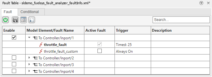
Open the Fault Table pane. In the Fault Analyzer tab, in the View section, click Fault Table.
Enable the first input port for the
To Controllersubsystem for fault injection. In the Enable column, select the check box for the model elementTo Controller/Inport/1.Expand the list for the To
Controller/Inport/1model element.Select
throttle_faultas the active fault on the first input port of theTo Controllersubsystem. In the Active Fault column, select the check box forthrottle_fault. Activatingthrottle_faultdisables the other fault,throttle_fault_custom.Enable fault simulation. In the Fault Table pane, click the turn on/off simulation of faults button. The icon is green when fault simulation is enabled.
Save the fault information file and the model. In the Fault Analyzer tab, in the File section, click Save All.