Getting Started with QSPI Communication for Infineon AURIX TC3x Microcontrollers
This example shows how to the use the QSPI Controller and QSPI Peripheral blocks from Embedded Coder® Support Package for Infineon® AURIX™ TC3x Microcontrollers to handle data through interrupts.
In this example, you will learn how to transmit and receive 5 bit data using the QSPI Controller block, QSPI Peripheral block, and interrupts.
Prerequisites
Complete the following examples:
Required Hardware
Infineon AURIX TC375 Lite Kit
Micro-USB cable
Hardware Connection
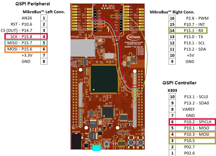
Connect the GPIO pins to mikro bus pins of Infineon AURIX TC375 Lite Kit hardware board as shown in this diagram.
Available Models
The example includes the preconfigured QSPI_TC375LK_example.slx model.

In this example, you map the transmit interrupt of the QSPI Controller block and the receiver interrupt of the QSPI Peripheral block to the Tx FIFO and Rx FIFO interrupts, respectively.

QSPI Controller Transmit
1. The QSPI Controller block triggers the |QSPI_TC375LK_example/TX_ISR subsystem every time it sends out data.

2. In this example, the TX FIFO mode parameter of QSPI controller block is set to Batch move. This mode triggers an interrupt whenever the filling level drops below the programmed threshold. When you set the TX FIFO threshold parameter to 1, the system generates an interrupt each time it transmits data from the transmit FIFO buffer.

QSPI Peripheral Receive
1. The QSPI Peripheral Rx subsystem handles the received data by triggering the QSPI_TC375LK_example.slx RX_ISR subsystem. Ensure that the output data length specified in the QSPI Peripheral Receive block matches the data that has been transmitted.

2. In this example, the RxFifo mode parameter of QSPI peripheral block is set to Batch move in this example. This mode triggers an interrupt whenever the filling level exceeds the programmed threshold. When you set the RxFifo mode threshold parameter to 1, the system generates an interrupt each time the receive FIFO buffer receives data.

Monitor and Tune the Model
1. Open the QSPI_TC375LK_example.slx model.
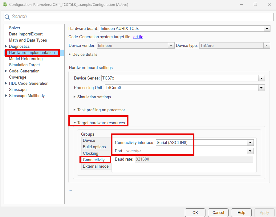
2. In your Simulink® model, press Ctrl+E or click Modeling > Model Settings to open the Configuration Parameters window. Navigate to Hardware Implementation > Target hardware resources > Connectivity. Set Connectivity interface to Serial(ASCLIN0) for external mode.
3. Select Serial port in MATLAB preferences in the Configuration Parameters window. To see a list of available COM ports on your computer, select Start > Control Panel > Device Manager > Ports (COM &LPT).
4. On the Hardware tab, click Monitor & Tune to configure the model for simulation. At this point, your model runs on the Infineon AURIX TC375 Lite Kit and communicates with Simulink so that you can monitor and tune the parameters.
5. Observe the received data in the Display block in the QSPI Peripheral Rx subsystem.
Other Things to Try
Run the example on different Infineon AURIX TC3x microcontrollers by changing the package class and pinout options and analyze the results.