Extrapolate EDSADC Output Using Timestamp Information
This example shows how to use the Enhanced Delta-Sigma Analog to Digital Converter (EDSADC) block from Embedded Coder® Support Package for Infineon® AURIX™ TC3x Microcontrollers to determine the accurate EDSADC output using its timestamp information.
Introduction
The EDSADC continuously provides the conversion output after every successful analog-to-digital conversion of the analog input signal at an output rate. The output rate depends on the EDSADC block parameters such as on-chip modulator frequency, decimation factor of the cascaded integrated-comb (CIC) filter, and the number of samples selected for integration, which you set in the Hardware Mapping tool. The EDSADC block is used in applications such as motor control applications that demand the analog to digital conversion results at specific points of time (main program cycle or application rate) that lie between two regular outputs in the conversion cycle time. You can extrapolate the accurate conversion result at the main program cycle by utilizing the previous conversion result, timestamp information (time elapsed from the previous conversion result), and the output rate of the EDSADC block.
Prerequisites
Complete the following examples:
Required Hardware
Infineon AURIX TC375 Lite Kit
Micro-USB cable
Signal generator for analog signal generation
Hardware Connection
Connect the signal generator to AN0 pin (channel 3) of Infineon AURIX TC375 Lite Kit.
Available Models
The example includes the preconfigured model ExtrapolateEDSADCReadingsUsingTimestampInformation, which you can use for external mode of simulation.
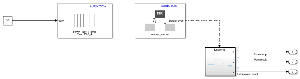
The model comprises of the PWM block and a Hardware Interrupt block with the function call subsystem. This figure illustrates the function call subsystem.

The PWM block signifies the application demanding the conversion results at the main program cycle. The application rate in this model is 500 microseconds as the Initial frequency parameter of the PWM block in Hardware Mapping tool is set to 2 kHz.
You can calculate the output rate using this formula: (On-chip modulator clock frequency/Decimation factor)/Number of values to accumulate. You can find the values of the three terms in the equation from the corresponding parameters in the Hardware Mapping tool. This model is configured to produce conversion output at every 92 microseconds.
The PWM timer module triggers the timestamp circuit in the EDSADC block at every 500 microseconds to obtain the conversion output. This PWM signal acts as a gate to trigger main filter result interrupt service routine, which extracts the timestamp information of the last conversion output.
Using extrapolation algorithms and by utilizing the inputs of previous conversion output, output rate, and timestamp information, the 1-D Lookup Table block provides the accurate conversion output at every 500 microseconds.
Configure the Model
1. Open the ExtrapolateEDSADCReadingsUsingTimestampInformation model.
2. Press Ctrl+E to open the Configuration Parameters dialog box. Click Hardware Implementation in the left pane and set Hardware board to Infineon AURIX™ TC3x.
3. Under Hardware board settings, expand Target hardware resources. Set the Series and Package class parameters to match your hardware.
4. Use the Hardware Mapping tool to observe the interrupts configured for the available blocks in this example.
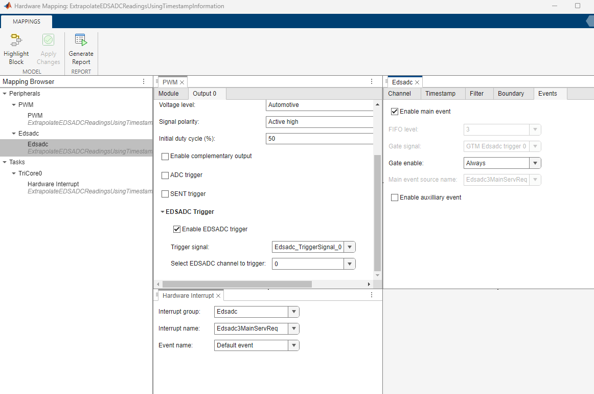
Generate Code and Deploy Model to Target Hardware
Complete the following steps to generate code and run the model on the target hardware.
1. Open the ExtrapolateEDSADCReadingsUsingTimestampInformation model.
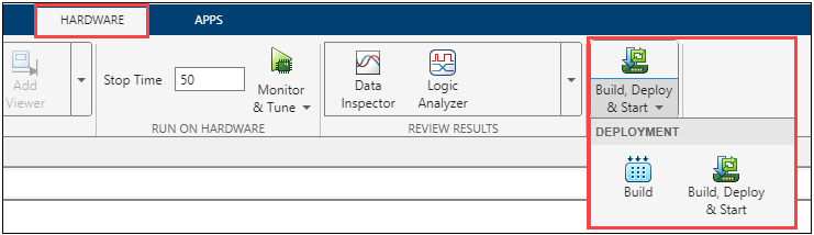
2. Click Build, Deploy & Start on the Hardware tab to deploy the target model to the hardware.
3. Follow the build process by opening the diagnostic viewer using the link provided at the bottom of the model canvas. You can observe the code generation report that contains code for model traceability. Infineon AURIX deploys the model to the hardware using a downloading tool.
Note: You can ignore the model advisor warning message while trying to build the model.

4. Download and install the One Eye tool from Infineon to monitor signals from the hardware. Before using the One Eye tool, ensure that you download and install the latest version of the TAS/DAS tool.
5. Open the One Eye tool. Load extrapolate_EDSADC_readings_using_timestamp_information.OneEye file shipped with this example by clicking File > Load Configuration in the One Eye tool.
6. Load the ExtrapolateEDSADCReadingsUsingTimestampInformation.elf file generated in Step 3 and observe the timestamp, conversion result, and extrapolated conversion values.
Other Things to Try
Run the example on different Infineon AURIX TC3x microcontrollers by changing the package class and pinout options and analyze the results.