Sensorless Field-Oriented Control of PMSM on Infineon AURIX Microcontrollers
R2026bThis example shows how to implement sensorless field-oriented control (FOC) of a permanent magnet synchronous motor (PMSM) using Embedded Coder® Support Package for Infineon® AURIX™ TC4x Microcontrollers.
The example uses an Extended EMF Observer (Motor Control Blockset) (EEMF) observer to estimate rotor position and speed, eliminating the need for a physical position sensor. The motor initially runs in open-loop control using the current-to-frequency (I-F) control algorithm. After the EEMF observer starts tracking the rotor position, the controller transitions to closed-loop FOC and uses the estimated values to control the motor.
Prerequisites
For more information on hardware setup and required third-party toolchains to compile the generated code, see Hardware Setup for Infineon AURIX Microcontrollers and Supported Hardware and Required Software.
For more information on deploying a Simulink model to a hardware board, see Getting Started with Embedded Coder Support Package for Infineon AURIX TC4x Microcontrollers.
Required Hardware
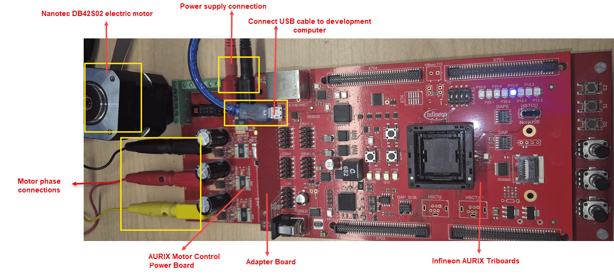
Infineon AURIX TC4x hardware board
Motor Control Power Board
Nanotec DB42S02 electric motor
Hardware Setup
Connect the hardware as shown in this diagram.
Model Description
Open the tc4x_mcb_pmsm_foc_sensorless model included with the example. The model supports both simulation and code generation.
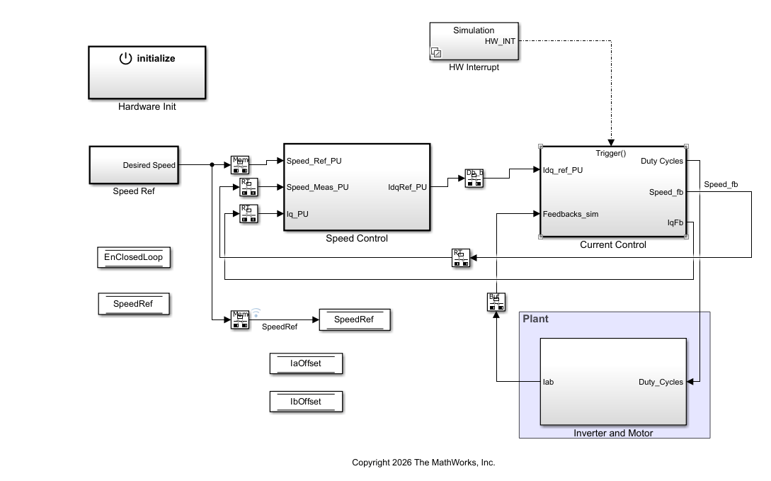
Speed Control ― The Speed Control subsystem implements the outer speed loop of the sensorless PMSM FOC algorithm. It compares the speed reference with the measured or estimated motor speed and uses a PI Controller (Motor Control Blockset) to generate the q-axis current reference for the inner current control loop. To support stable operation and smooth transitions between open-loop and closed-loop control modes, it implements rate limiting and anti-windup protection.
Current Control ― The Current Control subsystem performs the time-critical control functions of the sensorless PMSM FOC algorithm. It uses an EEMF observer to estimate the electrical angle and mechanical speed from measured phase currents and applied voltages. Because the EEMF observer cannot provide reliable position estimates at low speeds, the subsystem uses an I-F Controller (Motor Control Blockset) during startup. The motor initially operates in open loop until its speed reaches the transition threshold, pmsm.N_base * IFParam.SpeedToExitIF_PU, at which point the algorithm transitions to closed-loop sensorless FOC.
Depending on the motor and load characteristics, you can tune the I-F startup parameters in the tc4x_mcb_pmsm_foc_sensorless_data script provided with the example.
Configure Model
The example includes the
tc4x_mcb_pmsm_foc_sensorless_datascript, which defines the motor, inverter, and control parameters required for sensorless FOC of a PMSM. To configure the model for a different motor, modify the motor parameters in this script.The model is pre-configured for the Infineon AURIX TC4xx TriBoard. If you use an Infineon AURIX TC4xx Control Board, in the Hardware Mapping tool, update the pin assignments and ADC channel mappings to match your hardware connections. For more information, see Deploy Motor Control Applications to TC497N Control Board.
Simulate Model
Complete the following steps to simulate the model.
1. Open tc4x_mcb_pmsm_foc_sensorless model.
2. Configure the model for the Infineon AURIX development board. On the Modeling tab, click Model Settings to open the Configuration Parameters dialog box. In the Hardware Implementation pane, set Hardware board to Infineon AURIX. Set the Series and Package class parameters to match your hardware board. Click OK.
3. Simulate the model. In the Simulink® editor, on the Simulation tab, click Run.
4. View and analyze the simulation results. On the Simulation tab, click Data Inspector.
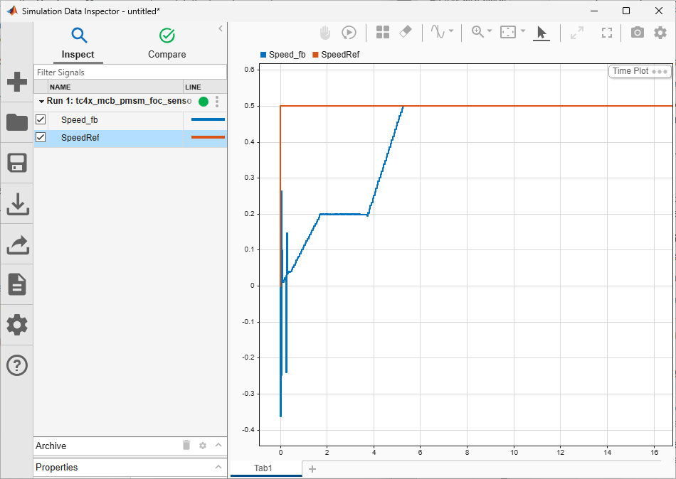
The following plot shows Speed_fb signal tracking SpeedRef signal. During I-F startup, the motor accelerates in open loop with transient oscillations. After transitioning to sensorless closed-loop control, Speed_fb accurately tracks SpeedRef.
Generate Code and Deploy Model to Target Hardware
Complete the following steps to generate code and run the sensorless FOC algorithm on the target hardware.
1. Complete the hardware connections.
2. Open tc4x_mcb_pmsm_foc_sensorless model.
3. Deploy the model to the hardware board. In the Simulink editor, on the Hardware tab, click Build, Deploy & Start. To follow the build process, open the diagnostic viewer using the link at the bottom of the model canvas.
4. To monitor run-time signals from the hardware, download and install the OneEye tool. Before using the OneEye tool, download and install the latest version of the tool access software/device access server (TAS/DAS) tool.
5. Open the OneEye tool and click File. To load the OneEye configuration file included in the example, click Load Configuration and select tc4x_mcb_pmsm_foc_sensorless.OneEye file.
6. To load the executable and linkable format (ELF) file generated in step 3, in the Debug box viewer pane, click Load ELF file. Select tc4x_mcb_pmsm_foc_sensorless.elf.
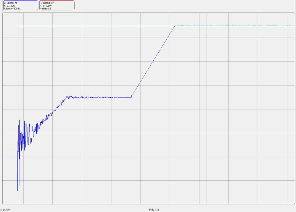
The plot shows Speed_fb signal tracking SpeedRef signal. During I-F startup, the motor accelerates in open loop with transient oscillations. After transitioning to sensorless closed-loop control, Speed_fb accurately tracks SpeedRef.
Other Things to Try
1. The example includes the tc4x_mcb_pmsm_foc_sensorless_data script. Use this script to:
Tune the I-F startup parameters to optimize the startup behavior for your specific motor and load conditions.
Tune the speed PI gains and observer cutoff frequency for faster transient response.
Change the reference speed and verify sensorless operation across the full operating range (20% to 100% of base speed).
2. Compare EEMF observer performance with encoder-based FOC from the Field-Oriented Control of PMSM with Encoder Using Infineon AURIX Microcontrollers example.
3. Replace the EEMF Observer with a Flux Observer (Motor Control Blockset) or Sliding Mode Observer (Motor Control Blockset) and compare sensorless performance using the Analyze Sensorless Observers for Field-Oriented Control Using Multiple Cores of Infineon AURIX example.
See Also
Sensorless Field-Oriented Control of PMSM (Motor Control Blockset)
Field-Oriented Control of PMSM with Encoder Using Infineon AURIX Microcontrollers
Analyze Sensorless Observers for Field-Oriented Control Using Multiple Cores of Infineon AURIX
Accelerate AI Based Software Development on Infineon AURIX TC4x Microcontroller

