Using Filter Designer
Filter Designer is a powerful user interface for designing and analyzing filters. Filter Designer enables you to quickly design digital FIR or IIR filters by setting filter performance specifications, by importing filters from your MATLAB® workspace or by adding, moving, or deleting poles and zeros. Filter Designer also provides tools for analyzing filters, such as magnitude and phase response plots and pole-zero plots.
Getting Started
To open filter designer, type
filterDesigner
A Tip of the Day dialog displays with suggestions for using Filter Designer. Then, the interface displays with a default filter.

The Filter Designer interface has three main regions:
The Current Filter Information region
The Filter Display region and
The Design panel
The upper half of the interface displays information on filter specifications and responses for the current filter. The Current Filter Information region, in the upper left, displays filter properties, namely the filter structure, order, number of sections used and whether the filter is stable or not. It also provides access to the Filter manager for working with multiple filters.
The Filter Display region, in the upper right, displays various filter responses, such as, magnitude response, group delay and filter coefficients.
The lower half of the interface is the interactive portion of Filter Designer. The Design Panel, in the lower half is where you define your filter specifications. It controls what is displayed in the other two upper regions. Other panels can be displayed in the lower half by using the sidebar buttons.
The tool includes Context-sensitive help. You can right-click or click the What's This? button to get information on the different parts of the tool.
Note that when you open filter designer, Design Filter is not enabled. You must make a change to the default filter design in order to enable Design Filter. This is true for each time you want to change the filter design. Changes to radio button items or drop down menu items such as those under Response Type or Filter Order enable Design Filter immediately. Changes to specifications in text boxes such as Fs, Fpass, and Fstop require you to click outside the text box to enable Design Filter.
Choosing a Response Type
You can choose from several response types:
Lowpass
Raised cosine
Highpass
Bandpass
Bandstop
Differentiator
Multiband
Hilbert transformer
Arbitrary magnitude
Arbitrary Group Delay
Peaking
Notching
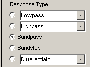
To design a bandpass filter, select the radio button next to Bandpass in the Response Type region of the app.
Note
Not all filter design methods are available for all response types. Once you choose your response type, this may restrict the filter design methods available to you. Filter design methods that are not available for a selected response type are removed from the Design Method region of the app.
Choosing a Filter Design Method
You can use the default filter design method for the response type that you've selected, or you can select a filter design method from the available FIR and IIR methods listed in the app.
To select the Remez algorithm to compute FIR filter coefficients, select the
FIR radio button and choose Equiripple from the
list of methods.

Setting the Filter Design Specifications
Viewing Filter Specifications
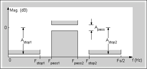
The filter design specifications that you can set vary according to response type and design method. The display region illustrates filter specifications when you select Analysis > Filter Specifications or when you click the Filter Specifications toolbar button.
You can also view the filter specifications on the Magnitude plot of a designed filter by selecting View > Specification Mask.
Filter Order
You have two mutually exclusive options for determining the filter order when you design an equiripple filter:
Specify order: You enter the filter order in a text box.
Minimum order: The filter design method determines the minimum order filter.
Select the Minimum order radio button for this example.

Note that filter order specification options depend on the filter design method you choose. Some filter methods may not have both options available.
Options
The available options depend on the selected filter design method. Only the FIR
Equiripple and FIR Window design methods have settable options. For FIR Equiripple, the
option is a Density Factor. See firpm for more information. For FIR Window the options are Scale
Passband, Window selection, and for the following
windows, a settable parameter:
Window | Parameter |
|---|---|
Chebyshev ( | Sidelobe attenuation |
Gaussian ( | Alpha |
Kaiser ( | Beta |
Taylor ( | Nbar and Sidelobe level |
Tukey ( | Alpha |
User Defined | Function Name, Parameter |
You can view the window in the Window Visualization Tool (WVTool) by clicking the View button.
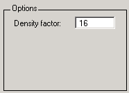
For this example, set the Density factor to
16.
Bandpass Filter Frequency Specifications
For a bandpass filter, you can set
Units of frequency:
Hz
kHz
MHz
GHz
Normalized (0 to 1)
Sampling frequency
Passband frequencies
Stopband frequencies
You specify the passband with two frequencies. The first frequency determines the lower edge of the passband, and the second frequency determines the upper edge of the passband.
Similarly, you specify the stopband with two frequencies. The first frequency determines the upper edge of the first stopband, and the second frequency determines the lower edge of the second stopband.
For this example:
Keep the units in Hz (default).
Set the sampling frequency (Fs) to
2000Hz.Set the end of the first stopband (Fstop1) to
200Hz.Set the beginning of the passband (Fpass1) to
300Hz.Set the end of the passband (Fpass2) to
700Hz.Set the beginning of the second stopband (Fstop2) to
800Hz.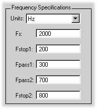
Bandpass Filter Magnitude Specifications
For a bandpass filter, you can specify the following magnitude response characteristics:
Units for the magnitude response (dB or linear)
Passband ripple
Stopband attenuation
For this example:
Keep Units in
dB(default).Set the passband ripple (Apass) to
0.1dB.Set the stopband attenuation for both stopbands (Astop1, Astop2) to
75dB.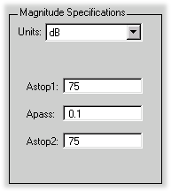
Computing the Filter Coefficients
Now that you've specified the filter design, click the Design Filter button to compute the filter coefficients.
Notice that the Design Filter button is disabled once you've computed the coefficients for your filter design. This button is enabled again once you make any changes to the filter specifications.
Analyzing the Filter
Displaying Filter Responses
You can view the following filter response characteristics in the display region or in a separate window.
Magnitude response
Phase response
Magnitude and Phase responses
Group delay response
Phase delay response
Impulse response
Step response
Pole-zero plot
Zero-phase response — available from the y-axis context menu in a Magnitude or Magnitude and Phase response plot.
Magnitude Response Estimate
Round-off Noise Power Spectrum
The Magnitude Response Estimate and Round-off Noise Power Spectrum analyses use filter internals.
You can display two responses in the same plot by selecting Analysis > Overlay Analysis and selecting an available response. A second y-axis is added to the right side of the response plot. (Note that not all responses can be overlaid on each other.)
You can also display the filter coefficients and detailed filter information in this region.
For all the analysis methods, except zero-phase response, you can access them from the Analysis menu, the Analysis Parameters dialog box from the context menu, or by using the toolbar buttons. For zero-phase, right-click the y-axis of the plot and select Zero-phase from the context menu.
![]()
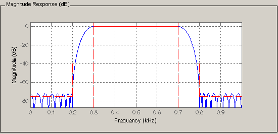
For example, to look at the filter's magnitude response, select the
Magnitude Response button ![]() on the toolbar.
on the toolbar.

You can also overlay the filter specifications on the Magnitude plot by selecting View > Specification Mask.
Note
You can use specification masks in FVTool only if FVTool was launched from filter designer.
Using Data Tips
You can click the response to add plot data tips that display information about particular points on the response.
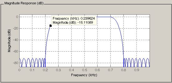
For information on using data tips, see Interactively Explore and Analyze Plotted Data.
Drawing Spectral Masks
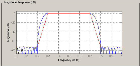
To add spectral masks or rejection area lines to your magnitude plot, click View > User-defined Spectral Mask.

The mask is defined by a frequency vector and a magnitude vector. These vectors must be the same length.
Enable Mask— Select to turn on the mask display.Normalized Frequency— Select to normalize the frequency between 0 and 1 across the displayed frequency range.Frequency Vector— Enter a vector of x-axis frequency values.Magnitude Units— Select the desired magnitude units. These units should match the units used in the magnitude plot.Magnitude Vector— Enter a vector of y-axis magnitude values.
The magnitude response below shows a spectral mask.
Changing the Sampling Frequency
To change the sampling frequency of your filter, right-click any filter response plot and select Sampling Frequency from the context menu.
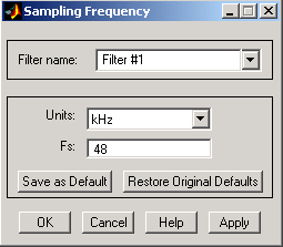
To change the filter name, type the new name in Filter name. (In FVTool, if you have multiple filters, select the desired filter and then enter the new name.)
To change the sampling frequency, select the desired unit from
Units and enter the sampling frequency in Fs.
(For each filter in fvtool, you can specify a different sampling
frequency or you can apply the sampling frequency to all filters.)
To save the displayed parameters as the default values to use when filter designer or FVTool is opened, click Save as Default.
To restore the default values, click Restore Original Defaults.
Displaying the Response in FVTool
To display the filter response characteristics in a separate window, select View > Filter Visualization Tool (available if any analysis, except the filter specifications, is in the
display region) or click the Full View Analysis
button:![]()
This launches the Filter Visualization Tool (fvtool).
Note
If Filter Specifications are shown in the display region, clicking the Full View Analysis toolbar button launches a MATLAB figure window instead of FVTool. For details, see Add Annotations to Chart. The associated menu item is Print to figure, which is enabled only if the filter specifications are displayed.
You can use this tool to annotate your design, view other filter characteristics, and print your filter response. You can link filter designer and fvtool so that changes made in filter designer are immediately reflected in fvtool. See FVTool for more information.

Editing the Filter Using the Pole/Zero Editor
Displaying the Pole-Zero Plot
You can edit a designed or imported filter's coefficients by moving, deleting, or adding poles and/or zeros using the Pole/Zero Editor panel.
Note
You cannot generate MATLAB code (File > Generate MATLAB code) if your filter was designed or edited with the Pole/Zero Editor.
You cannot move quantized poles and zeros. You can only move the reference poles and zeros.
Click the Pole/Zero Editor button in the sidebar or select Edit > Pole/Zero Editor to display this panel.

Poles are shown using x symbols and zeros are shown using o symbols.
Changing the Pole-Zero Plot
Plot mode buttons are located to the left of the pole/zero plot. Select one of the buttons to change the mode of the pole/zero plot. The Pole/Zero Editor has these buttons from left to right: move pole, add pole, add zero, and delete pole or zero.

The following plot parameters and controls are located to the left of the pole/zero plot and below the plot mode buttons.
Gain — factor to compensate for the filter's pole(s) and zero(s) gains
Coordinates — units (
PolarorRectangular) of the selected pole or zeroMagnitude — if polar coordinates is selected, magnitude of the selected pole or zero
Angle — if polar coordinates is selected, angle of selected pole(s) or zero(s)
Real — if rectangular coordinates is selected, real component of selected pole(s) or zero(s)
Imaginary — if rectangular coordinates is selected, imaginary component of selected pole or zero
Section — for multisection filters, number of the current section
Conjugate — creates a corresponding conjugate pole or zero or automatically selects the conjugate pole or zero if it already exists.
Auto update — immediately updates the displayed magnitude response when poles or zeros are added, moved, or deleted.
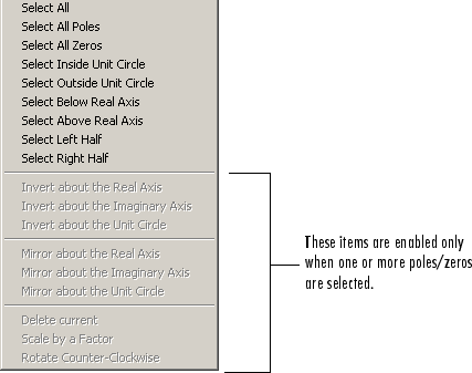
The Edit > Pole/Zero Editor has items for selecting multiple poles/zeros, for inverting and mirroring poles/zeros, and for deleting, scaling and rotating poles/zeros.
Moving one of the zeros on the vertical axis produces the following result:
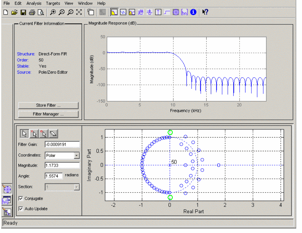
The selected zero pair is shown in green.
When you select one of the zeros from a conjugate pair, the Conjugate check box and the conjugate are automatically selected.
The Magnitude Response plot updates immediately because Auto update is active.
Converting the Filter Structure
Converting to a New Structure
You can use Edit > Convert Structure to convert the current filter to a new structure. All filters can be converted to the following representations:
Direct-form I
Direct-form II
Direct-form I transposed
Direct-form II transposed
Lattice ARMA
Note
If you have DSP System Toolbox™ product installed, you will see additional structures in the Convert structure dialog box.
In addition, the following conversions are available for particular classes of filters:
Minimum phase FIR filters can be converted to Lattice minimum phase
Maximum phase FIR filters can be converted to Lattice maximum phase
Allpass filters can be converted to Lattice allpass
IIR filters can be converted to Lattice ARMA
Note
Converting from one filter structure to another may produce a result with different characteristics than the original. This is due to the computer's finite-precision arithmetic and the variations in the conversion's roundoff computations.
For example:
Select Edit > Convert Structure to open the Convert structure dialog box.
Select
Direct-formIin the list of filter structures.
Converting to Second-Order Sections
You can use Edit > Convert to Second-Order Sections to store the converted filter structure as a collection of second-order sections rather than as a monolithic higher-order structure.
Note
The following options are also used for Edit > Reorder and Scale Second-Order Sections, which you use to modify an SOS filter structure.
The following Scale options are available when converting a direct-form II structure only:
None(default)L-2(L2 norm)L-infinity(L∞ norm)
The Direction (Up or Down)
determines the ordering of the second-order sections. The optimal ordering changes
depending on the Scale option selected.
For example:
Select Edit > Convert to Second-Order Sections to open the Convert to SOS dialog box.
Select
L-infinityfrom the Scale menu for L∞ norm scaling.Leave
Upas the Direction option.Note
To convert from second-order sections back to a single section, use Edit > Convert to Single Section.
Exporting a Filter Design
Exporting Coefficients or Objects to the Workspace
You can save the filter either as filter coefficients variables or as a filter System object™ variable. To save the filter to the MATLAB workspace:
Select File > Export. The Export dialog box appears.
Select
Workspacefrom the Export To menu.Select
Coefficientsfrom the Export As menu to save the filter coefficients or selectSystem Objectsto save the filter in a filter System object.For coefficients, assign variable names using the Numerator (for FIR filters) or Numerator and Denominator (for IIR filters), or SOS Matrix and Scale Values (for IIR filters in second-order section form) text boxes in the Variable Names region.
For System objects, assign the variable name in the Discrete Filter (or Quantized Filter) text box. If you have variables with the same names in your workspace and you want to overwrite them, select the Overwrite Variables check box.
Click the Export button.
Exporting Coefficients to an ASCII File
To save filter coefficients to a text file,
Select File > Export. The Export dialog box appears.
Select
CoefficientsFile(ASCII)from the Export To menu.Click the Export button. The Export Filter Coefficients to .FCF File dialog box appears.
Choose or enter a filename and click the Save button.
The coefficients are saved in the text file that you specified, and the MATLAB Editor opens to display the file. The text file also contains comments with the MATLAB version number, the Signal Processing Toolbox™ version number, and filter information.
Exporting Coefficients or Objects to a MAT-File
To save filter coefficients or a filter object as variables in a MAT-file:
Select File > Export. The Export dialog box appears.
Select
MAT-filefrom the Export To menu.Select
Coefficientsfrom the Export As menu to save the filter coefficients or selectObjectsto save the filter in a filter object.For coefficients, assign variable names using the Numerator (for FIR filters) or Numerator and Denominator (for IIR filters), or SOS Matrix and Scale Values (for IIR filters in second-order section form) text boxes in the Variable Names region.
For objects, assign the variable name in the Discrete Filter (or Quantized Filter) text box. If you have variables with the same names in your workspace and you want to overwrite them, select the Overwrite Variables check box.
Click the Export button. The Export to a MAT-File dialog box appears.
Choose or enter a filename and click the Save button.
Exporting to a Simulink Model
If you have the Simulink® product installed, you can export a Simulink block of your filter design and insert it into a new or existing Simulink model.
You can export a filter designed using any filter design method available in the filter designer app.
Note
If you have the DSP System Toolbox and Fixed-Point Designer™ installed, you can export a CIC filter to a Simulink model.
After designing your filter, click the Realize Model sidebar button or select File > Export to Simulink Model. The Realize Model panel is displayed.

Specify the name to use for your block in Block name.
To insert the block into the current (most recently selected) Simulink model, set the Destination to
Current. To inset the block into a new model, selectNew. To insert the block into a user-defined subsystem, selectUser defined.If you want to overwrite a block previously created from this panel, check Overwrite generated `Filter' block.
If you select the Build model using basic elements check box, your filter is created as a subsystem (Simulink) block, which uses separate sub-elements. In this mode, the following optimization(s) are available:
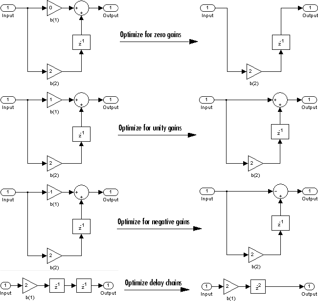
Optimize for zero gains— Removes zero-valued gain paths from the filter structure.Optimize for unity gains— Substitutes a wire (short circuit) for gains equal to 1 in the filter structure.Optimize for negative gains— Substitutes a wire (short circuit) for gains equal to -1 and changes corresponding additions to subtractions in the filter structure.Optimize delay chains— Substitutes delay chains composed ofnunit delays with a single delay ofn.Optimize for unity scale values— Removes multiplications for scale values equal to 1 from the filter structure.
The following illustration shows the effects of some of the optimizations:
Optimization Effects
Note
The Build model using basic elements check box is enabled only when you have a DSP System Toolbox license and your filter can be designed using digital filter blocks from that library.
Set the Input processing parameter to specify whether the generated filter performs sample- or frame-based processing on the input. Depending on the type of filter you design, one or both of the following options may be available:
Columns as channels (frame based)— When you select this option, the block treats each column of the input as a separate channel.Elements as channels (sample based)— When you select this option, the block treats each element of the input as a separate channel.
Click the Realize Model button to create the filter block. When the Build model using basic elements check box is selected, filter designer implements the filter as a subsystem block using Sum (Simulink), Gain (Simulink), and Delay (Simulink) blocks.
If you double-click the Simulink Filter block, the filter structure is displayed.
Other Ways to Export a Filter
You can also send your filter to a C header file or generate MATLAB code to construct your filter from the command line. For detailed instructions, see the following sections:
Generating a C Header File
You may want to include filter information in an external C program. To create a C header file with variables that contain filter parameter data, follow this procedure:
Select Targets > Generate C Header. The Generate C Header dialog box appears.

Enter the variable names to be used in the C header file. The particular filter structure determines the variables that are created in the file
Filter Structure
Variable Parameter
Direct-form I
Direct-form II
Direct-form I transposed
Direct-form II transposedNumerator, Numerator length*, Denominator, Denominator length*, and Number of sections (inactive if filter has only one section)
Lattice ARMA
Lattice coeffs, Lattice coeffs length*, Ladder coeffs, Ladder coeffs length*, Number of sections (inactive if filter has only one section)
Lattice MA
Lattice coeffs, Lattice coeffs length*, and Number of sections (inactive if filter has only one section)
Direct-form FIR Direct-form FIR transposed
Numerator, Numerator length*, and Number of sections (inactive if filter has only one section)
*length variables contain the total number of coefficients of that type.
Note
Variable names cannot be C language reserved words, such as “for.”
Select Export Suggested to use the suggested data type or select Export As and select the desired data type from the pull-down.
Note
If you do not have DSP System Toolbox software installed, selecting any data type other than double-precision floating point results in a filter that does not exactly match the one you designed in the filter designer. This is due to rounding and truncating differences.
Click Generate to generate the C header file. Click Close to close the dialog box.
Generating MATLAB Code
You can generate MATLAB code that constructs the filter you designed in filter designer from the command line. Select File > Generate MATLAB Code > Filter Design Function and specify the filename in the Generate MATLAB code dialog box.
Note
You cannot generate MATLAB code through File > Generate MATLAB Code > Filter Design Function (with System Objects) or through File > Generate MATLAB Code > Data Filtering Function (with System Objects), if your filter was designed or edited with the Pole/Zero Editor.
The following is generated MATLAB code when you choose File > Generate MATLAB Code > Data Filtering Function (with System Objects) for the equiripple bandpass filter designed in this example.
function Hd = ExFilter
%EXFILTER Returns a discrete-time filter object.

% MATLAB Code
% Generated by MATLAB(R) 9.1 and the DSP System Toolbox 9.3.
% Generated on: 17-Nov-2016 14:55:28

% Equiripple Bandpass filter designed using the FIRPM function.

% All frequency values are in Hz.
Fs = 2000;  % Sampling Frequency

Fstop1 = 200;              % First Stopband Frequency
Fpass1 = 300;              % First Passband Frequency
Fpass2 = 700;              % Second Passband Frequency
Fstop2 = 800;              % Second Stopband Frequency
Dstop1 = 0.000177827941;   % First Stopband Attenuation
Dpass  = 0.0057563991496;  % Passband Ripple
Dstop2 = 0.000177827941;   % Second Stopband Attenuation
dens   = 16;               % Density Factor

% Calculate the order from the parameters using FIRPMORD.
[N, Fo, Ao, W] = firpmord([Fstop1 Fpass1 Fpass2 Fstop2]/(Fs/2), [0 1 ...
    0], [Dstop1 Dpass Dstop2]);

% Calculate the coefficients using the FIRPM function.
b  = firpm(N, Fo, Ao, W, {dens});
Hd = dsp.FIRFilter( ...
    'Numerator', b);

% [EOF]
Managing Filters in the Current Session
You can store filters designed in the current filter designer session for cascading together, exporting to FVTool or for recalling later in the same or future filter designer sessions.
You store and access saved filters with the Store filter and Filter Manager buttons, respectively, in the Current Filter Information pane.
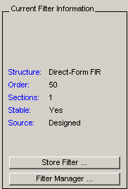
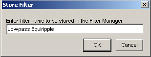
Store Filter — Displays the Store Filter dialog box in which you specify the filter name to use when storing the filter in the Filter Manager. The default name is the type of the filter.
Filter Manager — Opens the Filter Manager.

The current filter is listed below the listbox. To change the current filter, highlight the desired filter. If you select Edit current filter, filter designer displays the currently selected filter specifications. If you make any changes to the specifications, the stored filter is updated immediately.
To cascade two or more filters, highlight the desired filters and press Cascade. A new cascaded filter is added to the Filter Manager.
To change the name of a stored filter, press Rename. The Rename filter dialog box is displayed.
To remove a stored filter from the Filter Manager, press Delete.
To export one or more filters to FVTool, highlight the filter(s) and press FVTool.
Saving and Opening Filter Design Sessions
You can save your filter design session as a MAT-file and return to the same session another time.
Select the Save session button ![]() to save your session as a MAT-file. The first time you save
a session, a Save Filter Design Session browser opens, prompting you for a session
name.
to save your session as a MAT-file. The first time you save
a session, a Save Filter Design Session browser opens, prompting you for a session
name.
For example, save this design session as TestFilter.fda in your
current working directory by typing TestFilter in the File
name field.
The .fda extension is added automatically to all filter design
sessions you save.
Note
You can also use the File > Save session and File > Save session as to save a session.
You can load existing sessions into the Filter Design and Analysis Tool by selecting the
Open session button, ![]() or File > Open session. A Load Filter Design Session browser opens that allows you to select from
your previously saved filter design sessions.
or File > Open session. A Load Filter Design Session browser opens that allows you to select from
your previously saved filter design sessions.