firlpnorm
Least P-norm optimal FIR filter
Syntax
b = firlpnorm(n,f,edges,a)

b = firlpnorm(n,f,edges,a,w)

b = firlpnorm(n,f,edges,a,w,p)

b = firlpnorm(n,f,edges,a,w,p,dens)

b = firlpnorm(n,f,edges,a,w,p,dens,initnum)

b = firlpnorm(...,'minphase')

[b,err] = firlpnorm(...)
Description
b = firlpnorm(n,f,edges,a) returns
a filter of numerator order n which represents
the best approximation to the frequency response described by f and a in
the least-Pth norm sense. P is set to 128 by default, which essentially
equivalent to the infinity norm. Vector edges specifies
the band-edge frequencies for multiband designs. firlpnorm uses
an unconstrained quasi-Newton algorithm to design the specified filter.
f and a must have the
same number of elements, which can exceed the number of elements in edges.
This lets you specify filters with any gain contour within each band.
However, the frequencies in edges must also be
in vector f. Always use freqz to
check the resulting filter.
Note
firlpnorm uses a nonlinear optimization
routine that may not converge in some filter design cases. Furthermore
the algorithm is not well-suited for certain large-order (order >
100) filter designs.
b = firlpnorm(n,f,edges,a,w) uses
the weights in w to weight the error. w has one entry per frequency point (the same length as f and a)
which tells firlpnorm how much emphasis to put
on minimizing the error in the vicinity of each frequency point relative
to the other points. For example,
b = firlpnorm(20,[0 .15 .4 .5 1],[0 .4 .5 1],...
[1 1.6 1 0 0],[1 1 1 10 10])
designs a lowpass filter with a peak of 1.6 within the passband, and with emphasis placed on minimizing the error in the stopband.
b = firlpnorm(n,f,edges,a,w,p) where p is
a two-element vector [pmin pmax] lets you specify
the minimum and maximum values of p used in the
least-pth algorithm. Default is [2 128] which essentially
yields the L-infinity, or Chebyshev, norm. pmin and pmax should
be even numbers. The design algorithm starts optimizing the filter
with pmin and moves toward an optimal filter in
the pmax sense. When p is set
to 'inspect', firlpnorm does
not optimize the resulting filter. You might use this feature to inspect
the initial zero placement.
b = firlpnorm(n,f,edges,a,w,p,dens) specifies
the grid density dens used in the optimization.
The number of grid points is [dens*(n+1)]. The
default is 20. You can specify dens as a single-element
cell array. The grid is equally spaced.
b = firlpnorm(n,f,edges,a,w,p,dens,initnum) lets
you determine the initial estimate of the filter numerator coefficients
in vector initnum. This can prove helpful for difficult
optimization problems. The pole-zero editor in Signal Processing Toolbox™ software
can be used for generating initnum.
b = firlpnorm(...,'minphase') where
'minphase' is the last argument in the argument
list generates a minimum-phase FIR filter. By default, firlpnorm design
mixed-phase filters. Specifying input option 'minphase'
causes firlpnorm to use a different optimization
method to design the minimum-phase filter. As a result of the different
optimization used, the minimum-phase filter can yield slightly different
results.
[b,err] = firlpnorm(...) returns
the least-pth approximation error err.
Examples
Design a lowpass filter with a peak of 1.4 in the passband. The resulting filter is lowpass, with the desired 1.4 peak in the passband.
b = firlpnorm(22,[0 .15 .4 .5 1],[0 .4 .5 1],[1 1.4 1 0 0],...
[1 1 1 2 2]);
freqz(b)
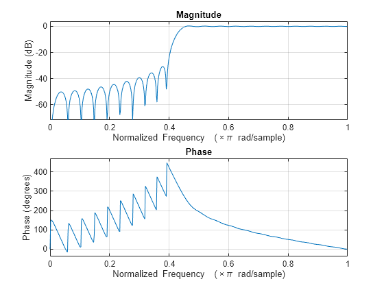
Design a highpass minimum-phase filter optimized for the 4-norm.
b = firlpnorm(44,[0 .4 .45 1],[0 .4 .45 1],[0 0 1 1],[5 1 1 1],...
[2 4],'minphase');
freqz(b)
The zero-pole plot shows the minimum phase nature more clearly.
zplane(b)

References
Saramaki, T, Finite Impulse Response Filter Design, Handbook for Digital Signal ProcessingMitra, S.K. and J.F. Kaiser Eds. Wiley-Interscience, N.Y., 1993, Chapter 4.
Extended Capabilities
Version History
Introduced in R2011a