Acquire Digital Data Using a Counter Output Channel as External Clock
This example shows how to use a device counter output channel to generate pulses to use as an external clock for acquiring digital data.
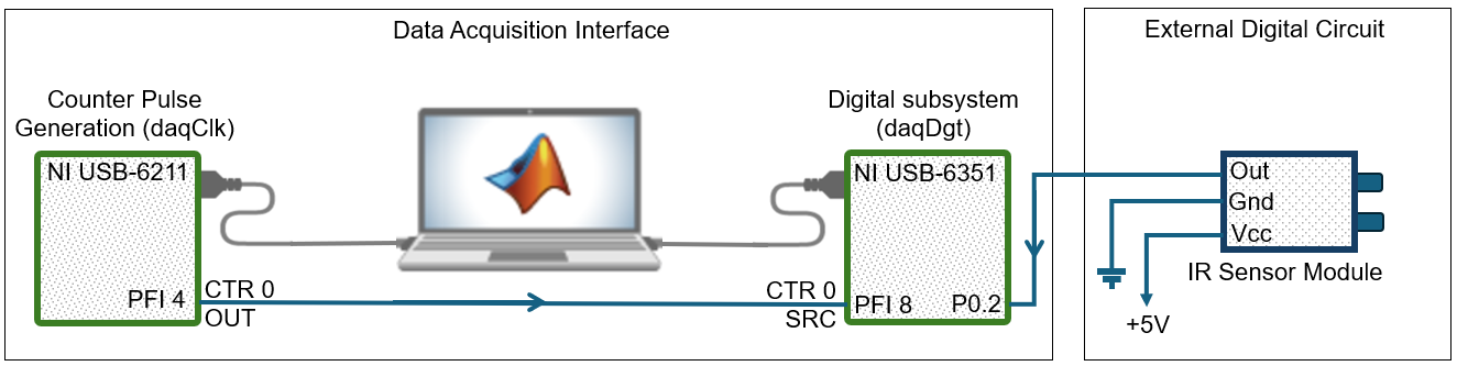
In this example, you generate a clock in one DataAcquisition object
using a counter output channel and export the clock to another
DataAcquisition object that acquires digital data. The counter
output and the digital subsystem can be on the same device or on different devices. If
using multiple devices not in the same chassis, you must wire a physical connection
between the counter output of one device to the digital clock input of the other.
Note
Importing an external clock does not automatically set the scan rate of your
DataAcquisition object. Manually set the Rate
property value of your DataAcquisition object to match the expected
external clock frequency.
Generate a Clock Using a Counter Output Channel
Create a clocked DataAcquisition interface
with a counter output channel that continuously generates frequency pulses in
the background. You can use this channel as an external clock for a clocked
digital acquisition.
Define the clock frequency to be used for synchronizing the scan rate of your counter output as well as the rate of your digital acquisition.
clockFreq = 100;
Create a DataAcquisition object and add a counter output channel for
PulseGeneration measurement type.
daqClk = daq("ni");
ch1 = addoutput(daqClk,"Dev1","ctr0","PulseGeneration");
Tip
Make sure the counter channel you add is not being used in a different
DataAcquisition object, otherwise a terminal
conflict error occurs.
View the counter output terminal ID. You must use it later to specify the external clock that synchronizes your digital clocked operations.
clkTerminal = ch1.Terminal
clkTerminal =

    'PFI4'
Set the frequency of your counter channel to the clock frequency.
ch1.Frequency = clockFreq;
Use Counter Clock to Acquire Clocked Digital Data
Create a DataAcquisition object for digital
input and use the counter output channel of another
DataAcquisition object as the external clock.
Create a DataAcquisition object and add a digital input line from port
0 line 2 on
Dev2.
daqDgt = daq("ni");
addinput(daqDgt,"Dev2","Port0/Line2","Digital")
Note
Not all devices support clocked digital I/O operations with hardware timing. For these
devices you can use software timed operations with single scan calls to read and
write.
Devices that support clocked digital I/O operations might not support them on all ports. Check your device specifications.
Tip
PFI terminal resources might be shared. Check your device routing in the NI MAX app.
Set the scan rate of your DataAcquisition object to the
same value as the rate of the counter output channel.
daqDgt.Rate = clockFreq;
Import the clock from your clocked DataAcquisition
interface to synchronize your acquisition.
addclock(daqDgt,"ScanClock","External","Dev2/PFI8")
Start the counter output channel to run continuously in the background.
start(daqClk,"Continuous")Pulse generation begins immediately on the counter output. It does not need data.
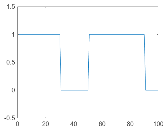
Acquire and plot digital input data.
dataIn = read(daqDgt,seconds(1),"OutputFormat","Matrix");
plot(dataIn(1:100,1))
axis([0 100 -0.5 1.5])
Stop the clocked DataAcquisition interface.
stop(daqClk)